[120] Local
reference
active
Output is high when 3-13 Reference Site =
[2] Local or when 3-13 Reference Site = [0]
Linked to hand auto at the same time as
the LCP is in [Hand on] mode.
Reference site set
in 3-13 Reference
Site
Local
refer-
ence
active
[120]
Remote
reference
active [121]
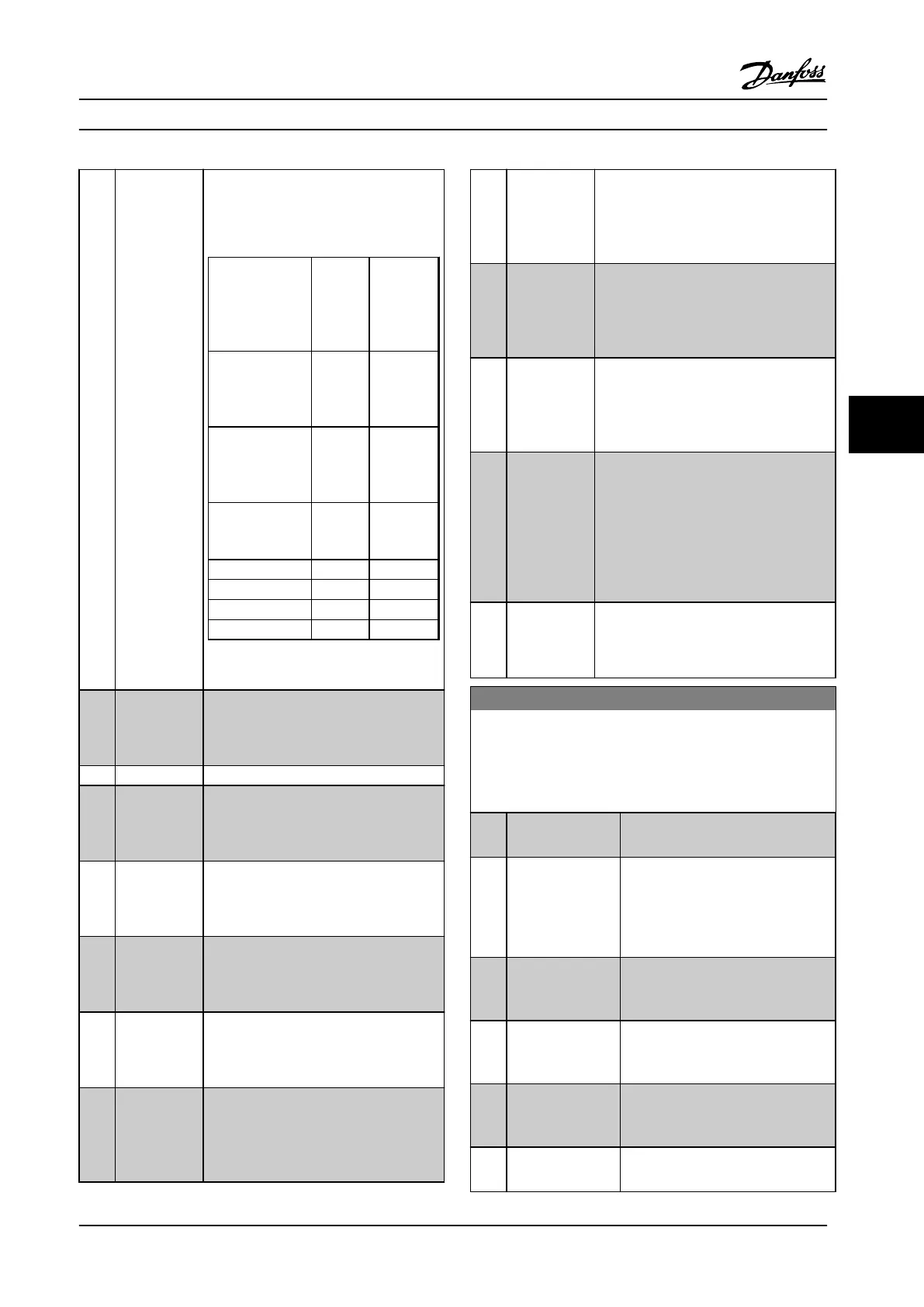
Reference site:
Local
3-13 Reference
Site [2]
1 0
Reference site:
Remote
3-13 Reference
Site [1]
0 1
Reference site:
Linked to Hand/
Auto
Hand 1 0
Hand ⇒ off
1 0
Auto ⇒ off
0 0
Auto 0 1
Table 6.8 Local and Remote Reference
[121]
Remote
reference
active
Output is high when 3-13 Reference Site
=[1] Remote or [0] Linked to hand/auto
while the LCP is in [Auto on] mode. See
Table 6.8.
[122] No alarm Output is high when no alarm is present.
[123] Start
command
active
Output is high when there is an active
start command (via digital input bus
connection or [Hand on] or [Auto on]), and
no stop or start command is active.
[124] Running
reverse
Output is high when the adjustable
frequency drive is running counter
clockwise (the logical product of the status
bits ‘running’ and ‘reverse’).
[125] Drive in hand
mode
Output is high when the adjustable
frequency drive is in hand on mode (as
indicated by the LED light above [Hand
on]).
[126] Drive in auto
mode
Output is high when the adjustable
frequency drive is in [Hand on] mode (as
indicated by the LED light above [Auto
on]).
[151] ATEX ETR cur.
alarm
Selectable if parameter 1-90 Motor Thermal
Protection is set to [20] Above feedback
high or [21] Thermal warning. If the alarm
164 ATEX ETR cur.lim.alarm is active, the
output is 1.
[152] ATEX ETR freq.
alarm
Selectable if parameter 1-90 Motor Thermal
Protection is set to [20] Above feedback
high or [21] Thermal warning. If the alarm
166 ATEX ETR freq.lim.alarm is active, the
output is 1.
[153] ATEX ETR cur.
warning
Selectable ifparameter 1-90 Motor Thermal
Protection is set to [20] Above feedback
high or [21] Thermal warning. If the alarm
163 ATEX ETR cur.lim.warning is active, the
output is 1.
[154] ATEX ETR freq.
warning
Selectable if parameter 1-90 Motor Thermal
Protection is set to [20] Above feedback
high or [21] Thermal warning. If the
warning 165 ATEX ETR freq.lim.warning is
active, the output is 1.
[188] AHF Capacitor
Connect
The capacitors are turned on at 20%
(hysteresis of 50% gives an interval of
10%–30%). The capacitors are discon-
nected below 10%. The off delay is 10 s
and restart if the nominal power goes
above 10% during the delay. 5-80 AHF Cap
Reconnect Delay is used to guarantee a
minimum off-time for the capacitors.
[189] External fan
control
The internal logic for the internal fan
control is transferred to this output to
make it possible to control an external fan
(relevant for HP duct cooling).
5-40 Function Relay
Array [9]
(Relay 1 [0], Relay 2 [1], Relay 3 [2] (MCB 113), Relay 4 [3] (MCB
113), Relay 5 [4] (MCB 113), Relay 6 [5] (MCB 113), Relay 7 [6]
(MCB 105), Relay 8 [7] (MCB 105), Relay 9 [8] (MCB 105))
Option: Function:
[0] No operation All digital and relay outputs are
default set to “No Operation.”
[1] Control ready The control card is ready. Control is
supplied by an external 24 V (MCB
107) and the main power to the
adjustable frequency drive is not
detected.
[2] Drive ready Adjustable frequency drive is ready to
operate. Line power and control
supplies are OK.
[3] Drive rdy/rem ctrl The adjustable frequency drive is
ready for operation and is in auto on
mode.
[4] Enable / no
warning
Ready for operation. No start or stop
commands have been applied (start/
disable). No warnings are active.
[5] Running Motor is running, and shaft torque
present.
Programming Instruction Manual
MG37A222 Danfoss A/S © Rev. 2014-02-07 All rights reserved. 71
6 6
 Loading...


