Refer to the three pins as 1, 2, and 3, reading bottom to top. Pins 1 and 2 of each connector are in parallel with the gate
drive signal sent to the IGBTs. Pin 1 is the signal and pin 2 is common.
1. Turn on the split bus power supply (only 650 V).
2. In stop mode, measure pins 1 and 2 of each test connector. A correct reading reading is approximately -9 V DC
which indicates that all IGBTs have been turned off.
3. Apply the run command to the adjustable frequency drive and 30 Hz reference.
4. If using a voltmeter, measure pins 1 and 2 of each connector. Waveform to IGBTs is a square wave that goes
positive to 14 V DC and negative to -9 V DC. Average voltage read by the voltmeter is 2.2 to 2.5 V DC.
14 13 12 11 10
9 8 7 6
5
4
1
2
3
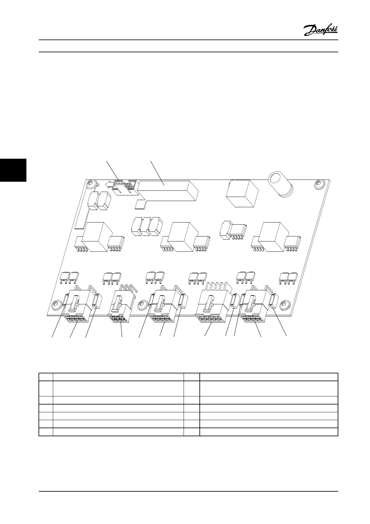
Figure 6.9 Gate Drive Card
1
MK102: Connection to inrush board 8 MK600: V phase upper IGBT test point
2 MK101: Gate drive and inrush control signals to the power
card
9 MK601: V phase IGBT gate signal
3 MK700: W phase upper IGBT test point 10 MIK602: V phase lower IGBT test point
4 MK701: W phase IGBT signal 11 MK100: IGBT temperature feedback
5 MK702: W phase lower IGBT test point 12 MK500: U phase upper IGBT test point
6 MK200: Brake IGBT test point (optional) 13 MK501: U phase IGBT gate signal
7 MK201: Brake IGBT gate signal (optional) 14 MK502: U phase lower IGBT test point
Table 6.5 Legend to Figure 6.9
Test Procedures
Service Manual
84 Danfoss A/S © Rev. 2014-02-10 All rights reserved. MG94A222
66
 Loading...


