3.11 Main Menu - Special Functions - Group
14
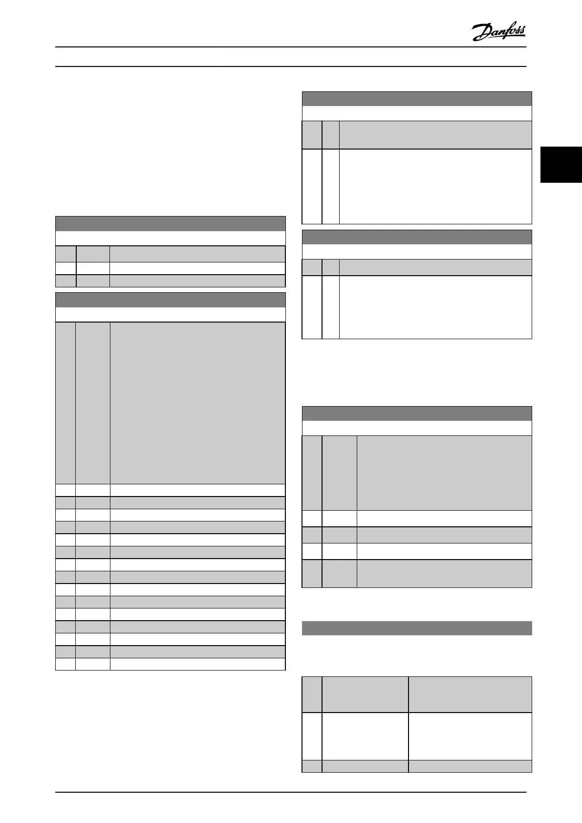
3.11.1 14-** Special Functions
Parameter group for configuring special frequency
converter
functions.
3.11.2 14-0* Inverter Switching
14-00 Switching Pattern
Option: Function:
Select the switching pattern: 60° AVM or SFAVM.
[0] * 60 AVM
[1] SFAVM
14-01 Switching Frequency
Option: Function:
Select the inverter switching frequency. Changing
the switching frequency can help to reduce
acoustic noise from the motor.
NOTE
The output frequency value of the
frequency converter must never exceed 1/10
of the switching frequency. When the motor
is running, adjust the switching frequency in
14-01 Switching Frequency until the motor is
as noiseless as possible. See also
14-00 Switching Pattern and the section
Derating.
[0] 1.0 kHz
[1] 1.5 kHz
[2] 2.0 kHz
[3] 2.5 kHz
[4] 3.0 kHz
[5] 3.5 kHz
[6] 4.0 kHz
[7] * 5.0 kHz
[8] 6.0 kHz
[9] 7.0 kHz
[10] 8.0 kHz
[11] 10.0 kHz
[12] 12.0kHz
[13] 14.0 kHz
[14] 16.0kHz
NOTE
Enabling
over-modulation can cause vibrations that may
destroy the mechanics if running in field weakening ares
(from 47 Hz).
14-03 Overmodulation
Option: Function:
[0] Off Selects no over-modulation of the output voltage in
order
to avoid torque ripple on the motor shaft.
[1] * On The over-modulation function generates an extra
voltage
of up-to 8% of U
max
output voltage without
over-modulation, which results in an extra torque of
10-12% in the middle of the over-syncronous range
(from 0% at nominal speed rising to approximately
12% at double nominal speed).
14-04 PWM Random
Option: Function:
[0] * Off No change of the acoustic motor switching noise.
[1] On Transforms the acoustic motor switching noise from a
clear
ringing tone to a less noticeable ‘white’ noise.
This is achieved by slightly and randomly altering the
synchronism of the pulse width modulated output
phases.
3.11.3 14-1* Mains On/Off
Parameters for configuring mains failure monitoring and
handling.
14-12 Function at Mains Imbalance
Option: Function:
Operation under severe main imbalance
conditions
reduces the lifetime of the motor.
Conditions are considered severe if the motor is
operated continuously near nominal load (e.g. a
pump or fan running near full speed).
When a severe mains imbalance is detected:
[0] * Trip
Select [0] Trip
to trip the frequency converter.
[1] Warning
Select [1] Warning
to issue a warning.
[2] Disabled
Select [2] Disabled
for no action.
[3] Derate
Select [3] Derate
for derating the frequency
converter.
Parameters for configuring auto reset handling, special trip
handling
and control card self test or initialisation.
14-20 Reset Mode
Select the reset function after tripping. Once reset, the frequency
converter
can be restarted.
Option: Function:
[0] * Manual reset
Select [0] Manual reset, to perform
a
reset via [Reset] or via the
digital inputs.
[1] Automatic reset x 1
Select [1]-[12]
Automatic reset x
1…x20 to perform between one
and twenty automatic resets after
tripping.
[2] Automatic reset x 2
Parameter Description
VLT
®
Refrigeration Drive Programming Guide
MG16H102 - VLT
®
is a registered Danfoss trademark
93
3 3
 Loading...


