3-16 Reference 2 Source
Option: Function:
[20] Digital pot.meter
[32] Bus PCD
3-17 Reference 3 Source
Option: Function:
Select the reference input to be used
for the rst reference signal.
Parameter 3-15 Reference 1 Source,
parameter 3-16 Reference 2 Source, and
parameter 3-17 Reference 3 Source
dene up to 3 dierent reference
signals. The sum of these reference
signals denes the actual reference.
[0] No function
[1] Analog Input 53
[2] Analog Input 54
[7] Frequency input
29
[8] Frequency input
33
[11] * Local bus
reference
[20] Digital pot.meter
[32] Bus PCD
3-18 Relative Scaling Reference Resource
Option: Function:
NOTICE
This parameter cannot be adjusted
while the motor is running.
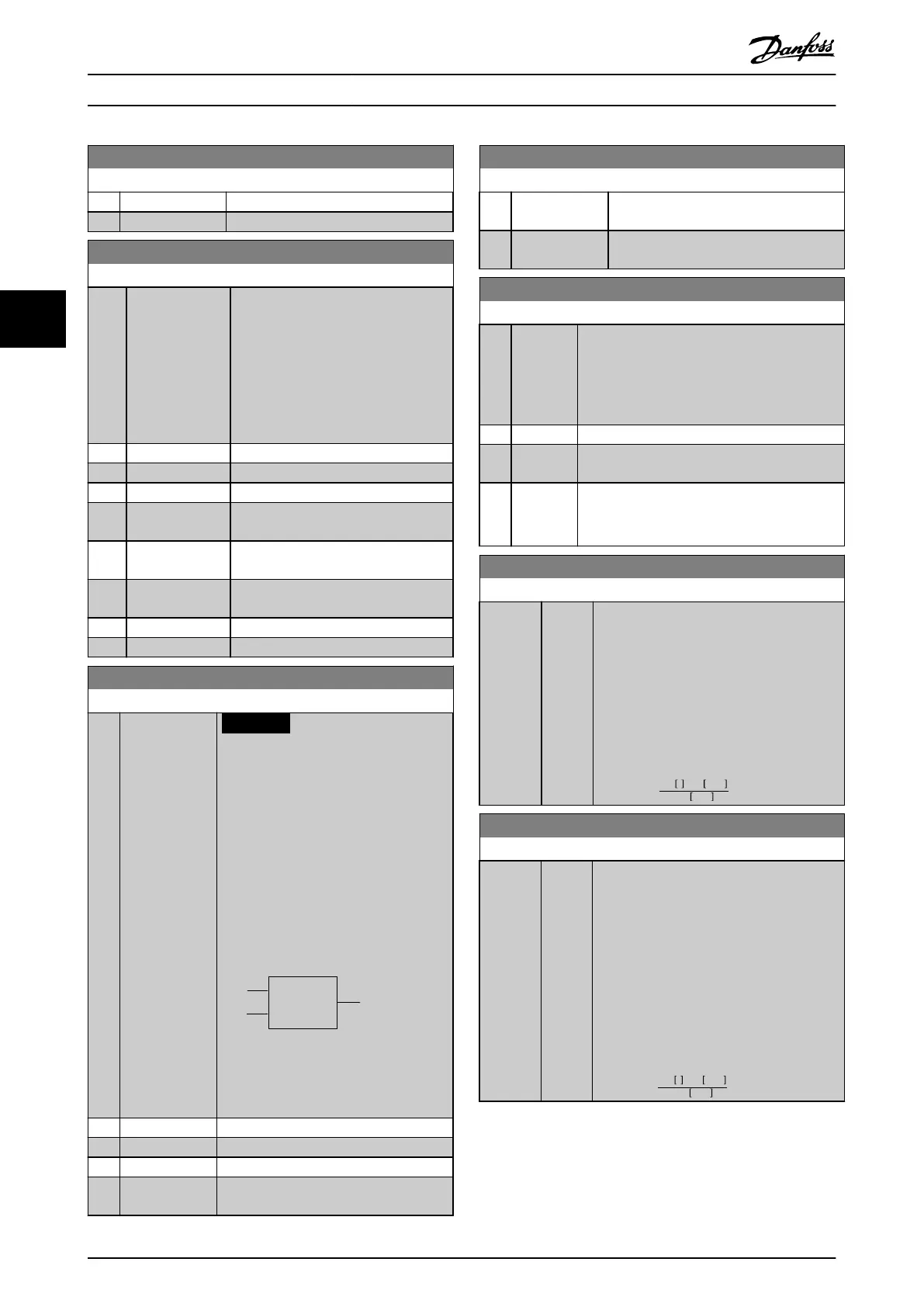
Select a variable value to be added to the
xed value (dened in
parameter 3-14 Preset Relative Reference).
The sum of the xed and variable values
(labeled Y in Illustration 4.5) is multiplied
by the actual reference (labeled X in
Illustration 4.5). This product is then
added to the actual reference (X+X*Y/100)
to give the resulting actual reference.
Relative
Z=X+X*Y/100
Resulting
actual
reference
Y
X
130BA059.12
Z
Illustration 4.5 Resulting Actual
Reference
[0] * No function
[1] Analog Input 53
[2] Analog Input 54
[7] Frequency input
29
3-18 Relative Scaling Reference Resource
Option: Function:
[8] Frequency input
33
[11] Local bus
reference
3-40 Ramp 1 Type
Option: Function:
Select the ramp type, depending on
requirements for acceleration/deceleration. A
linear ramp gives constant acceleration during
ramping. A sine-2 ramp gives non-linear
acceleration.
[0] * Linear
[1] Sine
Ramp
[2] Sine 2
Ramp
S-ramp based on the values set in
parameter 3-41 Ramp 1 Ramp Up Time and
parameter 3-42 Ramp 1 Ramp Down Time.
3-41 Ramp 1 Ramp Up Time
Range: Function:
Size
related*
[0.05 -
3600 s]
Enter the ramp-up time, that is the
acceleration time from 0 RPM to the
synchronous motor speed n
S
. Select a ramp-
up time such that the output current does
not exceed the current limit in
parameter 4-18 Current Limit during ramping.
The value 0.00 corresponds to 0.01 s in
speed mode. See ramp-down time in
parameter 3-42 Ramp 1 Ramp Down Time.
Par . 3 − 41 =
t
acc
s xn
s
RPM
ref RPM
3-42 Ramp 1 Ramp Down Time
Range: Function:
Size
related*
[0.05 -
3600 s]
Enter the ramp-down time, that is, the
deceleration time from the synchronous
motor speed n
s
to 0 RPM. Select a ramp-
down time such that no overvoltage occurs
in the inverter due to regenerative operation
of the motor, and such that the generated
current does not exceed the current limit set
in parameter 4-18 Current Limit. The value
0.00 corresponds to 0.01 s in speed mode.
See ramp-up time in parameter 3-41 Ramp 1
Ramp Up Time.
Par . 3 − 42 =
t
dec
s xn
s
RPM
ref RPM
Parameter Descriptions
VLT
®
Midi Drive FC 280
44 Danfoss A/S © 12/2015 All rights reserved. MG07C102
44
 Loading...


