3-10 Preset Reference
Range: Function:
0 %* [-100 -
100 %]
Enter up to 8 dierent preset references (0–7)
in this parameter, using array programming. For
selecting dedicated references, select preset
reference bit 0/1/2 [16], [17], or [18] for the
corresponding digital inputs in parameter
group 5-1* Digital Inputs.
3-11 Jog Speed [Hz]
Range: Function:
5 Hz* [ 0 - 400.0
Hz]
The jog speed is a xed output speed at
which the frequency converter runs when
the jog function is activated. See also
parameter 3-80 Jog Ramp Time.
3-12 Catch up/slow Down Value
Range: Function:
0 %* [0 -
100 %]
Enter a percentage value to be either added to or
deducted from the actual reference for catching
up or slowing down respectively. If [28] Catch up is
selected via 1 of the digital inputs
(parameter 5-10 Terminal 18 Digital Input to
parameter 5-15 Terminal 33 Digital Input), the
percentage value is added to the total reference. If
[29] Slow down is selected via 1 of the digital
inputs (parameter 5-10 Terminal 18 Digital Input to
parameter 5-15 Terminal 33 Digital Input), the
percentage value is deducted from the total
reference.
3-14 Preset Relative Reference
Range: Function:
0 %* [-100 -
100 %]
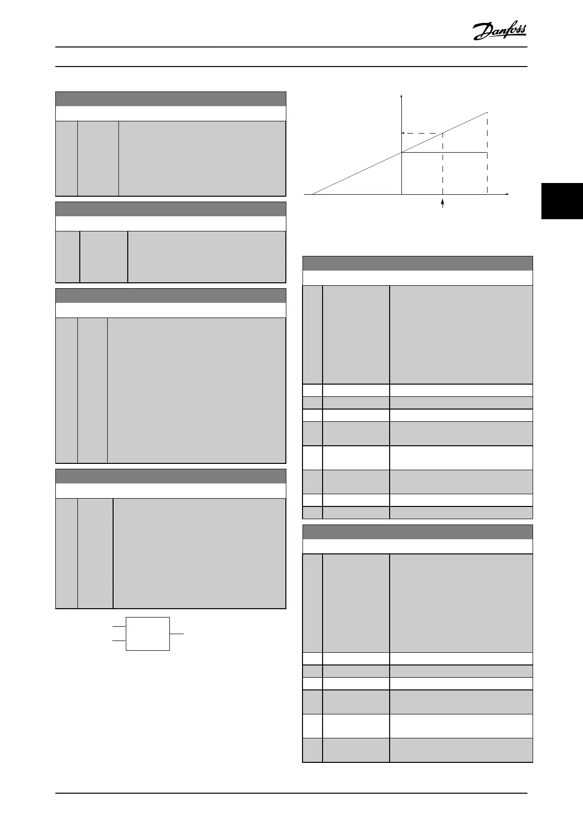
The actual reference, X, is increased or decreased
with the percentage Y, set in
parameter 3-14 Preset Relative Reference. This
results in the actual reference Z. Actual reference
(X) is the sum of the inputs selected in
parameter 3-15 Reference 1 Source,
parameter 3-16 Reference 2 Source,
parameter 3-17 Reference 3 Source, and
parameter 8-02 Control Source.
Relative
Z=X+X*Y/100
Resulting
actual
reference
Y
X
130BA059.12
Z
Illustration 4.3 Preset Relative Reference
X
100
%
0-100
Z
Y
X+X*Y/100
P 3-14
130BA278.10
Illustration 4.4 Actual Reference
3-15 Reference 1 Source
Option: Function:
Select the reference input to be used
for the rst reference signal.
Parameter 3-15 Reference 1 Source,
parameter 3-16 Reference 2 Source, and
parameter 3-17 Reference 3 Source dene
up to 3 dierent reference signals. The
sum of these reference signals denes
the actual reference.
[0] No function
[1] * Analog Input 53
[2] Analog Input 54
[7] Frequency input
29
[8] Frequency input
33
[11] Local bus
reference
[20] Digital pot.meter
[32] Bus PCD
3-16 Reference 2 Source
Option: Function:
Select the reference input to be used
for the rst reference signal.
Parameter 3-15 Reference 1 Source,
parameter 3-16 Reference 2 Source, and
parameter 3-17 Reference 3 Source dene
up to 3 dierent reference signals. The
sum of these reference signals denes
the actual reference.
[0] No function
[1] Analog Input 53
[2] * Analog Input 54
[7] Frequency input
29
[8] Frequency input
33
[11] Local bus
reference
Parameter Descriptions Programming Guide
MG07C102 Danfoss A/S © 12/2015 All rights reserved. 43
4 4
 Loading...


