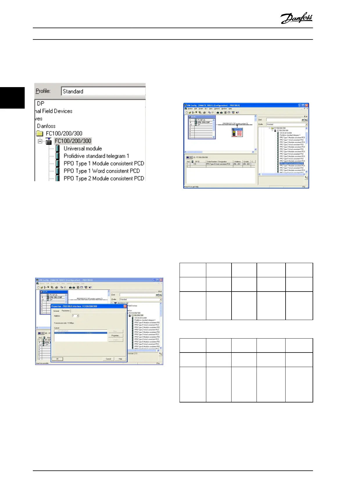
4. Import and access the FC 301/FC 302 GSD le via
the path in the hardware catalog, see
Illustration 3.6.
Illustration 3.6 Import and Access the GSD File
5. Open a project, set up the hardware, and add a
PROFIBUS master system.
6. Select FC 300, then drag and drop it onto the
PROFIBUS in the hardware diagram.
7. A window for the address of the FC 300 appears.
Select the address from the scroll-down list.
Ensure that the address setting matches the
previous address setting in parameter 9-18 Node
Address. See Illustration 3.7.
Illustration 3.7 Select the Address
8. Set up the peripheral input and output data. Data
set up in the peripheral area is transmitted
cyclically via PPO types. Drag and drop a PPO
type 6 word consistent to the rst slot, see
Illustration 3.8. See the PPO types in
chapter 4 Control for more information.
Illustration 3.8 Drag and Drop PPO Type 6 Word Consistent to
the First Slot
The conguration tool automatically assigns addresses in
the peripheral address area. In this example, the input and
output areas have the following congurations:
PPO type 6
PCD word
number
1 2 3 4
Input
address
256–257 258–259 260–261 262–263
Set-up STW MAV Parameter 9-
16 PCD Read
Congu-
ration.2
Parameter 9-
16 PCD
Read Cong-
uration.3
Table 3.3 PCD Read (Frequency Converter to PLC)
PCD word
number
1 2 3 4
Output
address
256–257 258–259 260–261 262–263
Set-up CTW MRV Parameter 9-
15 PCD Write
Congu-
ration.2
Parameter 9-
15 PCD
Write
Congu-
ration.3
Table 3.4 PCD Write (PLC to Frequency Converter)
Conguration
VLT
®
PROFIBUS DP MCA 101
10 Danfoss A/S © 01/2016 All rights reserved. MG37G202
33

 Loading...


