EasyManua.ls Logo

Danfoss VLT PROFIBUS DP MCA 101 User Manual

Danfoss VLT PROFIBUS DP MCA 101
64 pages
To Next Page IconTo Next Page
To Previous Page IconTo Previous Page
Page #34 background imageLoading...
Page #34 background image
batched. Therefore, when the master sends out a read/
write request, it must wait for the response before it sends
a new request. The request or response data value is
limited to maximum 4 bytes (see RC characteristics in
Table 5.14), which implies that text strings are not
transferable. For further information, see
chapter 7 Application Examples.
5.3.2 PCA - Parameter Characteristics
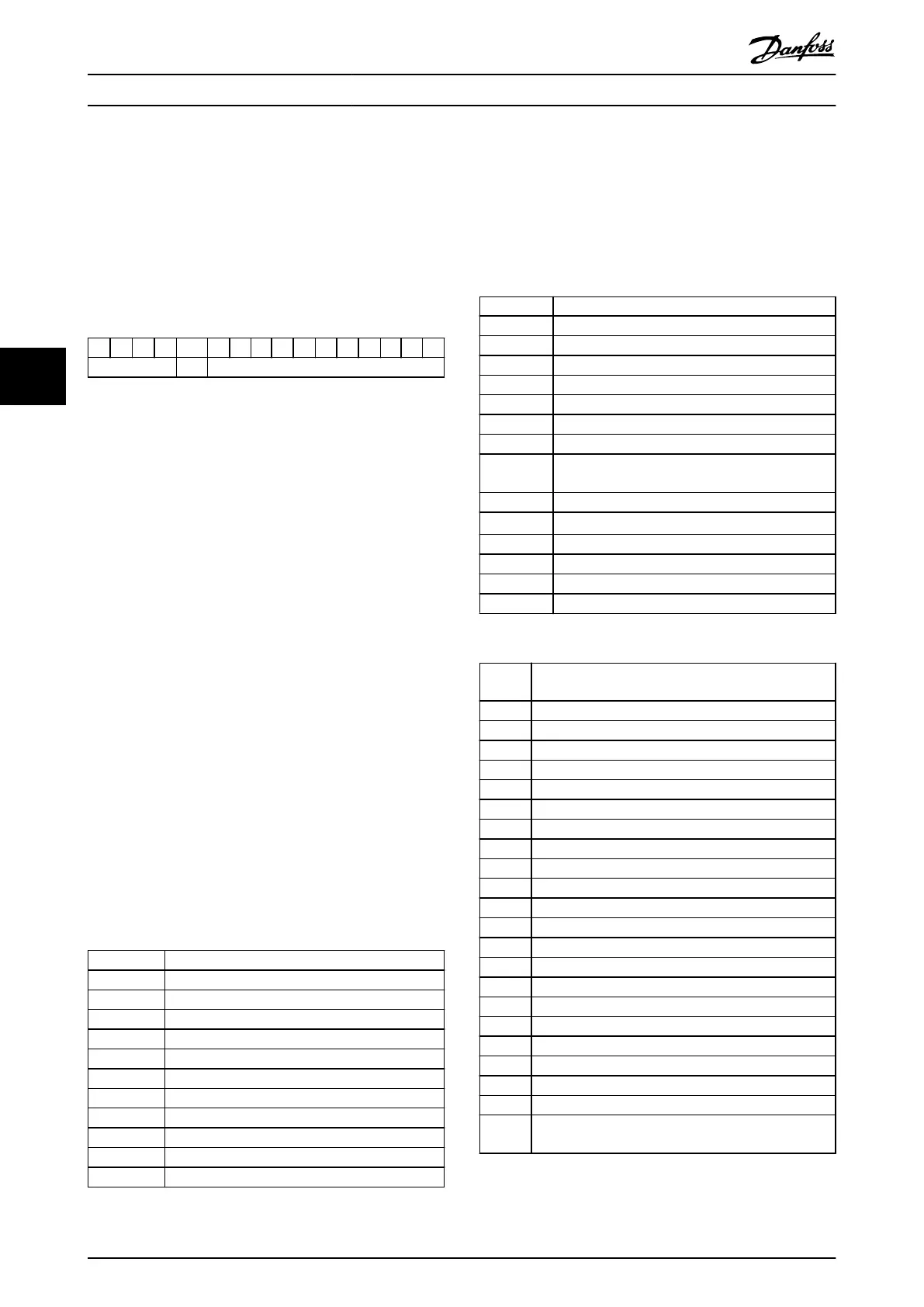
15 14 13 12 11 10 9 8 7 6 5 4 3 2 1 0
RC SMP PNU
Table 5.14 PCA - Parameter Characteristics
RC: Request/response characteristics (range 0–15).
SMP: Spontaneous message (not supported).
PNU: Parameter no. (range 1–1999).
5.3.3 Request/Response Handling
The RC portion of the PCA word denes:
The requests issued from the master to the slave.
Other portions of the PCV involved:
- PVA: The PVA portion transmits word-
size parameter values in bytes 7 and 8,
while long word size values require
bytes 5–8 (32 bits).
- IND: When the response/request
contains array elements, the IND carries
the array subindex. When parameter
descriptions are involved, the IND holds
the record subindex of the parameter
description.
5.3.4 RC Content
Request
The content of the RC portion of the PCA word for a
request is listed in Table 5.15.
Request Function
0 No request.
1 Request parameter value.
2 Change parameter value (word).
3 Change parameter value (long word).
4 Request description element.
5 Change description element.
6 Request parameter value (array).
7 Change parameter value (array word).
8 Change parameter value (array long word).
9 Request number of array elements.
10–15 Not used.
Table 5.15 Request
Response
When the slave rejects a request from the master, the RC
word in the PPO-read indicates the rejection by assuming
the value 7. Bytes 7 and 8 in the PVA element carry the
fault number.
The content of the RC portion of the PCA word for a
response is listed in Table 5.16.
Response Function
0 No response.
1 Transfer parameter value (word).
2 Transfer parameter value (long word).
3 Transfer description element.
4 Transfer parameter value (array word).
5 Transfer parameter value (array long word).
6 Transfer number of array elements.
7 Request rejected (including fault number, see
Table 5.17).
8 Not serviceable by PCV interface.
9 Not used.
10 Not used.
11 Not used.
12 Not used.
13–15 Not used.
Table 5.16 Response
Fault
number
Interpretation
0 Illegal PNU.
1 Parameter value cannot be changed.
2 Upper or lower limit exceeded.
3 Subindex corrupted.
4 No array.
5 Data type false.
6 Cannot be set by user (reset only).
7 Description element cannot be changed.
8 IR required PPO-write not available.
9 Description data not available.
10 Access group.
11 No parameter write access.
12 Key word missing.
13 Text in cyclic transmission not readable.
14 Name in cyclic transmission not readable.
15 Text array not available.
16 PPO-write missing.
17 Request temporarily rejected.
18 Other fault.
19 Data in cyclic transmission not readable.
130 There is no bus access to the parameter called.
131 Data change is not possible because factory set-up is
selected.
Table 5.17 Fault Numbers
Parameter Access
VLT
®
PROFIBUS DP MCA 101
32 Danfoss A/S © 01/2016 All rights reserved. MG37G202
55

Table of Contents

Other manuals for Danfoss VLT PROFIBUS DP MCA 101

Question and Answer IconNeed help?

Do you have a question about the Danfoss VLT PROFIBUS DP MCA 101 and is the answer not in the manual?

Danfoss VLT PROFIBUS DP MCA 101 Specifications

General IconGeneral
ModelVLT PROFIBUS DP MCA 101
ProtocolPROFIBUS DP
Communication ProtocolPROFIBUS DP
Humidity5% to 95% (non-condensing)
Protection ClassIP 20
CategoryMedia Converter
CompatibilityVLT AutomationDrive FC 302
Baud Rate9.6 kbit/s to 12 Mbit/s
Power Supply24 V DC
IsolationGalvanic isolation
Operating Temperature-10°C to 50°C

Summary

2 Safety

2.1 Safety Symbols

Defines warning symbols used in the manual to indicate potential hazards and precautions.

2.2 Qualified Personnel

Specifies requirements for personnel authorized to install, operate, and maintain the frequency converter safely.

2.3 Safety Precautions

Details critical safety warnings related to high voltage, unintended starts, and discharge time for safe operation.

3 Configuration

3.1 Configure the PROFIBUS Network

Guides on ensuring unique station addresses for all PROFIBUS devices on the network.

3.1.1 Setting the PROFIBUS Address using the DIP Switches

Describes how to set the PROFIBUS address for the frequency converter using hardware DIP switches.

3.2 Configure the Master

Explains the process of configuring the PROFIBUS master using a GSD file for the frequency converter series.

3.2.1 GSD File

Details the necessity and import procedure of the GSD file for PROFIBUS master configuration.

3.3 Configure the Frequency Converter

Outlines key parameters for configuring the frequency converter with a PROFIBUS interface.

3.3.1 Frequency Converter Parameters

Lists important parameters for PROFIBUS configuration, including control word, timeout, and diagnostic settings.

4 Control

4.1 PPO Types

Describes Parameter Process Data Objects (PPO) for data exchange between a process controller and a frequency converter.

4.3 Control Profile

Guides on selecting the control profile, PROFIdrive or Danfoss FC, affecting control and status words.

5 Parameter Access

5.1 Parameter Access in General

Covers general methods for accessing frequency converter parameters from PLCs or HMI equipment.

5.1.3 PROFIBUS DP-V1

Introduces PROFIBUS DP-V1 for acyclic communication, enabling parameter value reading and writing.

5.1.4 PROFIBUS DP VO/PCV Channel

Explains parameter access via the PCV channel, part of PPO types for cyclic data exchange.

5.2 DP-V1 Parameter Access

Guides on using DP-V1 for acyclic communication with PROFIBUS masters class 1 and 2.

5.2.1 PROFIBUS DP-V1 Introduction

Introduces DP-V1 extension for acyclic communication, enabling parameter access beyond DP-V0.

5.2.6 DP-V1 Features for Parameter Access

Describes how to use DP-V1 for accessing frequency converter parameters via the PROFIdrive parameter channel.

5.2.7 DP-V1 Read/Write Services

Lists DP-V1 command/response headers and their attributes for parameter access.

5.2.8 DP-V1 Acyclic Parameter Channel

Details the PROFIdrive parameter channel for reading/writing parameter values and attributes.

5.2.9 Request/Response Attributes

Overviews possible attributes of the PROFIdrive parameter channel for data access.

5.3 PCV Parameter Access

Details using the PCV channel for parameter access and status retrieval.

8 Troubleshooting

8.1 Diagnosis

Explains how VLT® PROFIBUS DP MCA 101 facilitates slave diagnosis through diagnosis messages.

8.2 No Response to Control Signals

Guides on troubleshooting lack of response to control signals by checking control word validity and terminal I/Os.

8.3 Warnings and Alarms

Lists and explains warning and alarm types, including their hex format and corresponding parameters.

8.4 Fault Messages via DP Diagnosis

Describes how standard DP diagnosis features provide online diagnosis during initialization and data exchange.

8.5 Extended Diagnosis

Details receiving extended diagnosis, alarm, and warning information based on trigger settings.

Related product manuals