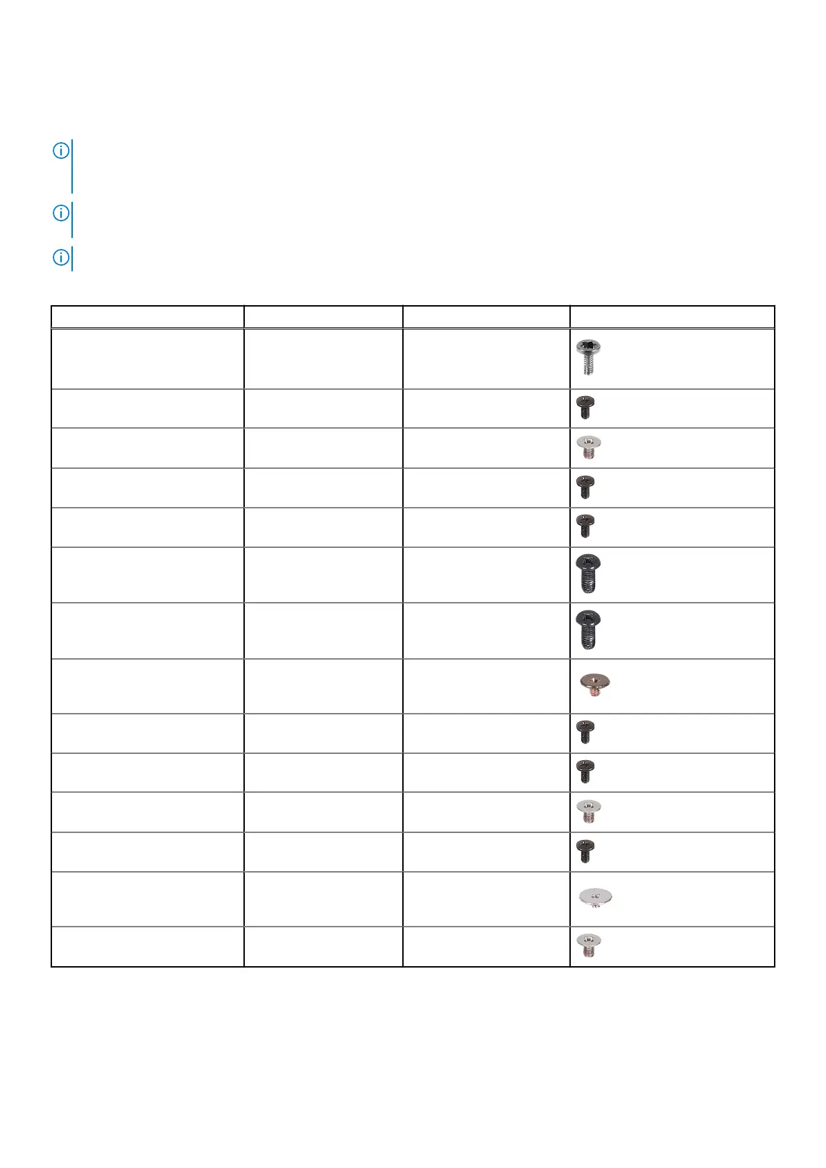
Screw list
NOTE: When removing screws from a component, it is recommended to note the screw type, the quantity of screws, and
then place them in a screw storage box. This is to ensure that the correct number of screws and correct screw type is
restored when the component is replaced.
NOTE: Some computers have magnetic surfaces. Ensure that the screws are not left attached to such surfaces when
replacing a component.
NOTE: Screw color may vary with the configuration ordered.
Table 26. Screw list
Component Screw type Quantity Screw image
Base cover M2x4, T5 8
Battery M2x4.5 6
Solid state drive thermal shield M2x3 3
CPU fan M2x4.5 3
GPU fan M2x4.5 3
Right hinge M2.5x6 2
Left hinge M2.5x6 2
Power button with fingerprint
reader
M1.4x1.5 4
Right Type-C bracket M2x4.5 2
Left Type C bracket M2x4.5 3
WLAN bracket M2x3 1
System board M2x4.5 4
Display-assembly cable bracket
holder
M1.4x1.3 2
Display-assembly cable bracket M2x3 2
Major components of XPS 16 9640
The following image shows the major components of XPS 16 9640.
Working inside your computer
31
 Loading...