13. Open the latch and disconnect the I/O board cable from the system board
14. Disconnect the fan cable from the system board.
15. Remove the two screws (M2x1.8) that secure the system board to the palm-rest and keyboard assembly.
16. Lift the system board at angle off the palm-rest and keyboard assembly, to clear the ports from the port openings.
Installing the system board
Prerequisites
CAUTION: The information in this section is intended for authorized service technicians only.
If you are replacing a component, remove the existing component before performing the installation process.
About this task
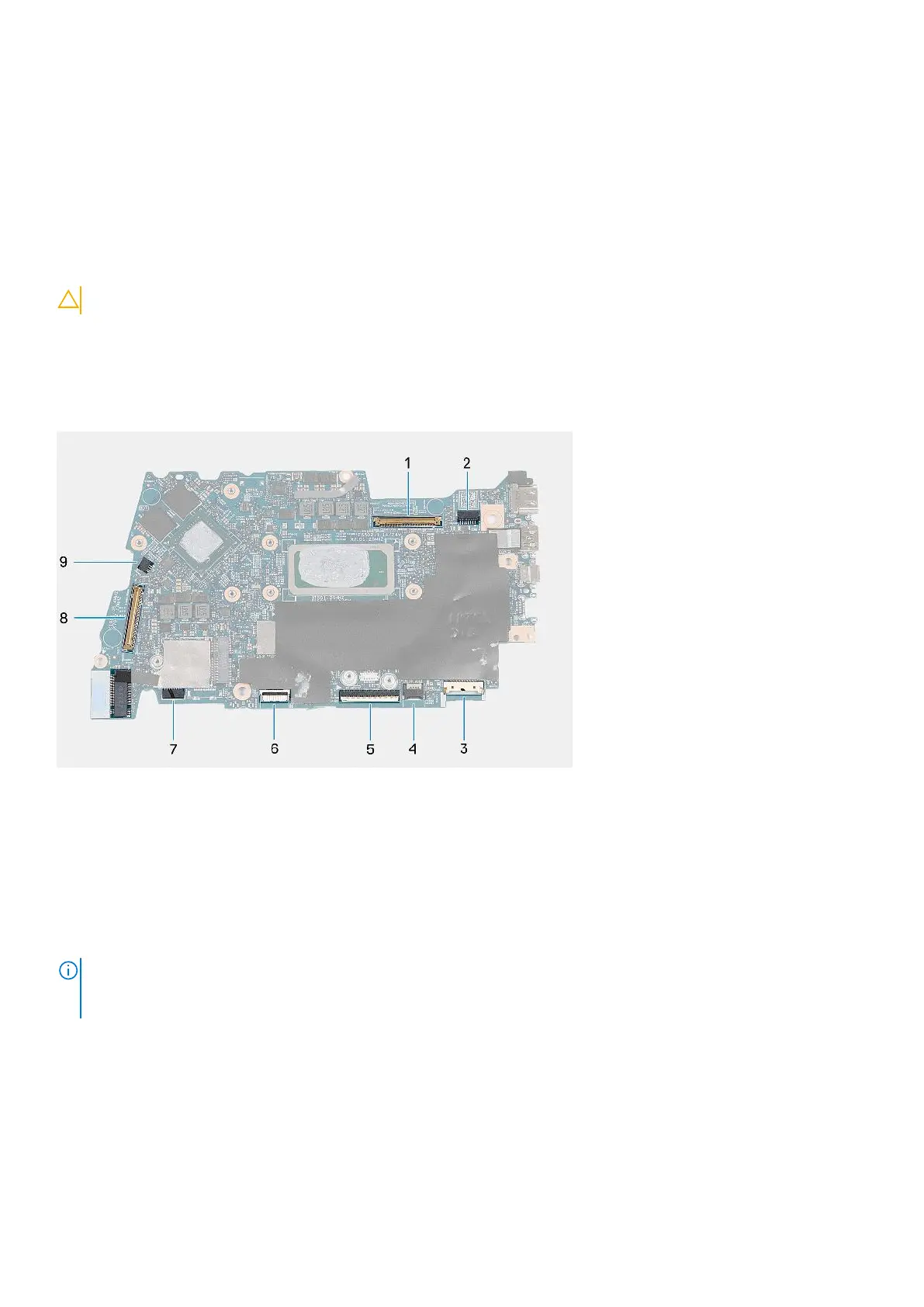
The following image(s) indicate the location of the system board and provides a visual representation of the installation
procedure.
1. Display cable connector
2. Power-cable connector
3. Battery-cable connector
4. Keyboard-cable connector
5. Touchpad-cable connector
6. Keyboard-backlight cable connector
7. Speaker cable connector
8. I/O board-cable connector
9. Fan-cable connector
NOTE:
The system board can be removed and installed along with the heat sink, when you replace the palm-rest and
keyboard assembly. This simplifies the removal and installation procedure and also prevents damage to the thermal bond
between the system board and heat sink.
Removing and installing Field Replaceable Units (FRUs) 67
 Loading...