EasyManua.ls Logo

Delta AS02HC-A User Manual

Delta AS02HC-A
632 pages
To Next Page IconTo Next Page
To Previous Page IconTo Previous Page
Page #177 background image
Chapter 6 Temperature Measurement Module AS04/06RTD
6- 19
6_
*1. Use shielded twisted pair cables for temperature sensors, and keep them away from power cables
and other cables that generate noise.
*2. If using two-wire temperature sensors, Ln- and In- must be short-circuited (where n is between 1–4).
*3. There are two different internal excitation currents. If you are using a Ni100 temperature sensor, a
Pt100 sensor, a JPt100, a Cu50/Cu100, or a 0~300 Ω resistance sensor, the internal excitation
current is 1.5 mA. If you are using a Ni1000 temperature sensor, a Pt1000 temperature sensor, a LG-
Ni1000 sensor, or a 0~3000 Ω resistance sensor, the internal excitation current is 0.2 mA.
Note: When using a three-wire temperature sensor, the cables should be the same length (less than 200
meter) and with a resistor less than 20 ohm.
(2) AS06RTD-A
Ni 100Pt1 00 ,J Pt1 00 ,
Cu 5 0, C u100 /
Ni 1000, P t1 0 00 ,
LG -Ni10 00 *3
,
AD C
A G
IN A
CH1
2-Wi re
CH 2
3-Wi re
L1 +
L 1-
0~ 300
Ni100 /Ni1000/ Pt100/Pt 1000
Cu50/C u100/JPt 100/ LG -Ni1000
Ω , 0~3000Ω
L2+
L2-
I12-
Shielde d c able 1*
Shielde d c able 1*
SLD
*2
*1. Use shielded twisted pair cables for temperature sensors and keep them away from power cables and
other cables that generate noise.
*2. Terminal “I12-“ indicates “ I1- & I2-“, terminal “I34-“ indicates “ I3- & I4-“, and terminal “I56-“ indicates
“ I5- & I6-“. If you use two-wire temperature sensors, Ln- and In- must be short-circuited (where n is
between 1–6).
*3. There are two different internal excitation currents. If you are using a Ni100 temperature sensor, a
Pt100 sensor, a JPt100, a Cu50/Cu100, or a 0~300 Ω resistance sensor, the internal excitation
current is 1.0 mA. If you are using a Ni1000 temperature sensor, a Pt1000 temperature sensor, a LG-
Ni1000 sensor, or a 0~3000 Ω resistance sensor, the internal excitation current is 0.2 mA.
Note: When using a three-wire temperature sensor, the cables should be the same length (less than 200
meter) and with a resistor less than 20 ohm.

Table of Contents

Question and Answer IconNeed help?

Do you have a question about the Delta AS02HC-A and is the answer not in the manual?

Delta AS02HC-A Specifications

General IconGeneral
BrandDelta
ModelAS02HC-A
CategoryNetwork Hardware
LanguageEnglish

Summary

Chapter 1 Introduction

1.3 Installation

Provides step-by-step instructions for installing modules, terminal blocks, and extension cards.

Chapter 2 Digital Input/Output Modules

2.1 Digital Input/Output Module Specifications

Details the electrical and functional specifications for digital input/output modules.

Chapter 3 Analog Input Module AS04/08AD

3.2 Specifications and Functions

Covers detailed electrical and functional specifications for analog input modules.

3.2.7 Wiring

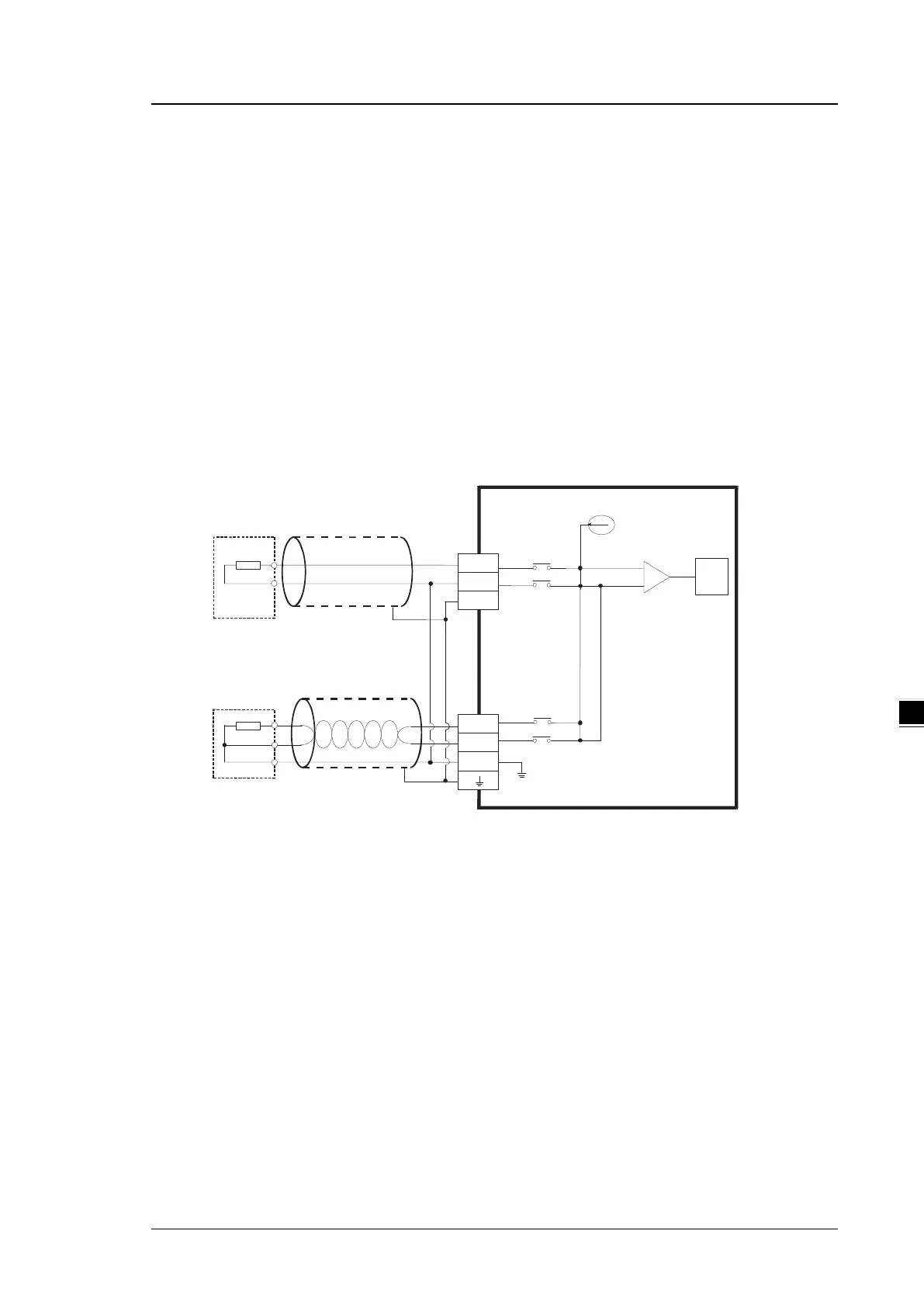
Provides detailed precautions and external wiring diagrams for analog input modules.

3.3 HWCONFIG in ISPSoft

Guides on using HWCONFIG software for module configuration, including initial setup, version check, and online mode.

3.4 DIADesigner+ (Hardware Configuration)

Guides on using DIADesigner+ for hardware configuration, including initial setup, module addition, and parameter settings.

3.5 Troubleshooting

Provides information on error codes and troubleshooting procedures for common issues.

Chapter 4 Analog Output Module AS04DA

4.2 Specifications and Functions

Covers detailed electrical and functional specifications for the AS04DA analog output module.

4.2.6 Wiring

Provides detailed precautions and external wiring diagrams for the AS04DA analog output module.

4.3 HWCONFIG in ISPSoft

Guides on using HWCONFIG software for module configuration, including initial setup, version check, and online mode.

4.4 DIADesigner+ (Hardware Configuration)

Guides on using DIADesigner+ for hardware configuration, including initial setup, module addition, and parameter settings.

4.5 Troubleshooting

Provides information on error codes and troubleshooting procedures for common issues.

Chapter 5 Analog Input/Output Module AS06XA

5.2 Specifications and Functions

Covers detailed electrical and functional specifications for the AS06XA analog input/output module.

5.2.6 Wiring

Provides detailed precautions and external wiring diagrams for the AS06XA analog input/output module.

5.3 HWCONFIG in ISPSoft

Guides on using HWCONFIG software for module configuration, including initial setup, version check, and online mode.

5.4 DIADesigner+ (Hardware Configuration)

Guides on using DIADesigner+ for hardware configuration, including initial setup, module addition, and parameter settings.

5.5 Troubleshooting

Provides information on error codes and troubleshooting procedures for common issues.

Chapter 6 Temperature Measurement Module AS04/06RTD

6.2 Specifications and Functions

Covers detailed electrical and functional specifications for temperature measurement modules.

6.2.8 Wiring

Provides detailed precautions and external wiring diagrams for temperature measurement modules.

6.3 HWCONFIG in ISPSoft

Guides on using HWCONFIG software for module configuration, including initial setup, version check, and online mode.

6.4 DIADesigner+ (Hardware Configuration)

Guides on using DIADesigner+ for hardware configuration, including initial setup, module addition, and parameter settings.

6.5 Troubleshooting

Provides information on error codes and troubleshooting procedures for common issues.

Chapter 7 Temperature Measurement Module AS04/08TC

7.2 Specifications and Functions

Covers detailed electrical and functional specifications for temperature measurement modules.

7.2.8 Wiring

Provides detailed precautions and external wiring diagrams for temperature measurement modules.

7.3 HWCONFIG in ISPSoft

Guides on using HWCONFIG software for module configuration, including initial setup, version check, and online mode.

7.4 DIADesigner+ (Hardware Configuration)

Guides on using DIADesigner+ for hardware configuration, including initial setup, module addition, and parameter settings.

7.5 Troubleshooting

Provides information on error codes and troubleshooting procedures for common issues.

Chapter 8 Load Cell Module AS02LC

8.2 Specifications

Covers detailed electrical specifications for the AS02LC load cell module.

8.2.6 Wiring

Provides external wiring diagrams for four-wire and six-wire load cell connections.

8.3 Making Adjustments

Guides on making adjustments to the load cell module, including steps for adjusting points and using the LC Wizard.

8.5 Troubleshooting

Provides information on error codes and troubleshooting procedures for common issues.

Chapter 9 Serial Communication Module AS00SCM

9.7 Error Codes

Lists error codes for AS00SCM-A when acting as a communication module or remote module.

Chapter 10 Function Cards

Chapter 11 DeviceNet Master Scanner Module AS01DNET-A

Chapter 12 Positioning Module AS02/04

12.4 Troubleshooting

Provides information on error codes and troubleshooting procedures for common issues.

Chapter 13 IO-Link Communication Module AS04SIL

Chapter 14 High Speed Counter Module AS02HC

14.5 Troubleshooting

Provides information on error codes and troubleshooting procedures for common issues.

Related product manuals