AS Series Module Manual
3- 6
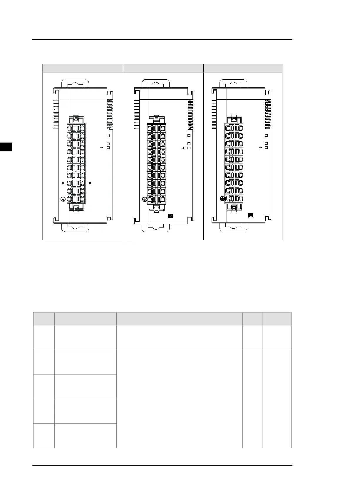
3.2.3 Arrangement of Terminals
04AD
V1+
AG
SLD
I3+
VI3
-
VI1
-
V3+
I1+
V2+
0V
24V
SLD
I4+
VI4
-
VI2
-
V4+
I2+
PWR
ERR
A D
3.2.4 AS04AD Control Register
*If you use HWCONFIG to set values in CRs, once the set value is downloaded, the values can be retained in
the module; however if you use TO instruction to write data into CRs, the values CANNOT be retained, after
power failure or after transition of the CPU from STOP to RUN.
Note: The attribute of the CR must be W (write) to use TO instruction.
CR# Name Description
Atr. Defaults
0
Format Setup
0: integer format
1: floating point format
R 0
1
Channel 1 mode setup
0: closed
1: -10 V to +10 V
2: 0 V–10 V
3: -5 V to +5 V
4: 0 V–5 V
5: 1 V–5 V
6: 0 mA–20 mA
7: 4 mA–20 mA
R/W 1
2
Channel 2 mode setup
3
Channel 3 mode setup
4
Channel 4 mode setup
24V
0V
AG
A D
ERR
PWR
V2+V1+
08AD
V1
-
V2
-
V3
-
V3+
V4
-
V4+
V5
-
V5+
V6
-
V6+
V7
-
V7+
V8
-
V8+
AG
0V
24V
PWR
ERR
A D
08AD
I1+ I2+
I1
-
I2
-
I4+
I4
-
I3+
I3
-
I5
-
I5+
I6
-
I6+
I7
-
I7+ I8+
I8
-
 Loading...