Chapter 13 IO-Link Communication Module AS04SIL
13-7
Number Name Description
4
Arrangement of the input/output
terminals
Arrangement of the terminals
Removal of the terminal block
Secures the module onto the DIN rail
8
Label Nameplate
13.2.3
Wiring
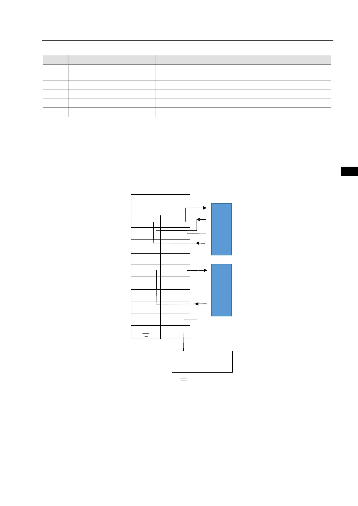
13.2.3.1 IO-Link Mode Wiring for Power and Communication
Precautions:
1. Keep the input cables, output cables and power cable separate from one another. It is suggested to use independent
power for AS04SIL-A. See the example below.
IO-Link Master
AS04S IL-A
CQ1 L1+
DI1 L1-
CQ2 L2+
DI2 L2-
CQ3 L3+
DI3 L3-
CQ4 L4+
DI4 L4-
. 24V
0V
1 Brown
3 Blue
4 Black
1 Brown
3 Blue
4 Black
2 White
IO-Link Sens or
(w ith DI)
IO-Link Sensor
DC Power S upply
24VD C
24V
0V
.
.
.
.
.
.
.
(w ithout DI)
2. The 24 VDC cable should be twisted and connected to a module within a short distance.
3. Do not bundle 110 VAC cable, 220 VAC cable, 24 VDC cable, the (high-voltage high-current) main circuit, and the I/O
signal cable together and keep the power cables away from the earth cable. It is suggested that the distance between
adjacent cables should be more than 100 millimeters.
4. Connect a cable with a diameter of 14 AWG or higher to ground.
5. Use single-wire cables or two-wire cables with a diameter of 20 AWG to 14 AWG. Only use copper conducting wires
with a temperature rating of 60/75°C.
 Loading...