Chapter 3 Analog Input Module AS04/08AD-A
3- 21
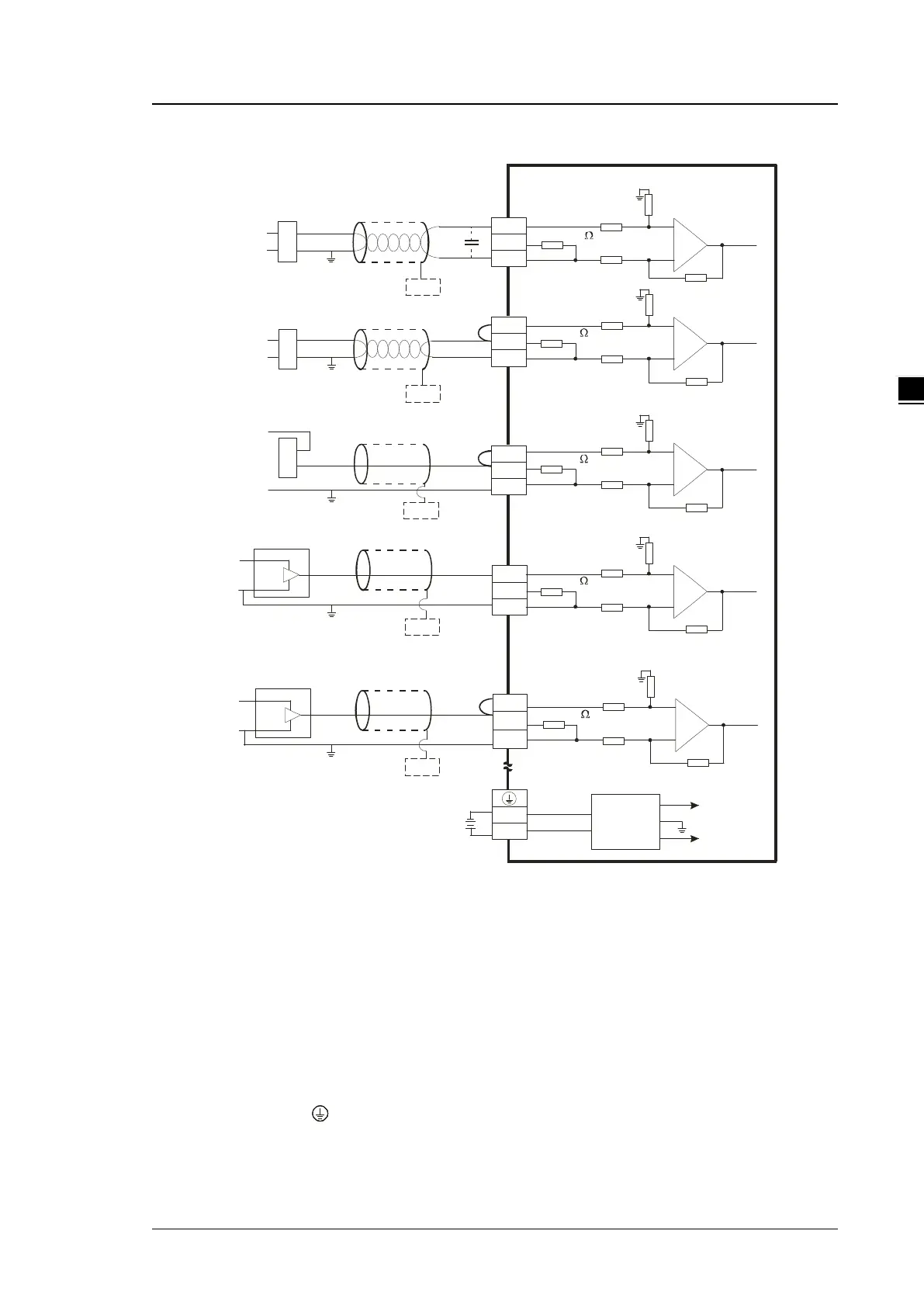
AS04AD-A External wiring
Shi elded cable *1
-10 V~ + 10 V
V I+
I1 +
VI 1-
C H X
V 3+
I3 +
V I3 -
*3
* 2
C H 1
1 M
C H 3
AG
1M
1M
A G
1 M
2 5 0
25 0
0 V
24 V
24 VD C
D C /D C
C on ve rte r
+ 15 V
-15 V
A G
FE
*4
*5
+
-
-20 mA ~ +2 0 mA
V 2+
I2 +
V I2 -
* 2
C H 2
1M
A G
1 M
25 0
*4
FE
+
-
+
-
+ 24 V
0 V
V4 +
I 4+
V I4 -
C H 4
1M
A G
1 M
25 0
+ 2 4V
0V
4 mA ~ +2 0m A
C H 1
1M
A G
1M
25 0
-2 0m A~ + 20 m A
+ 24 V
+
-
V 1+
I1 +
V I1 -
*2
-1 0 V~ + 10 V
+ 2 4V
+
-
* 4
FE
*4
FE
*4
FE
0 V
+ 2 4V
0 V
0V
*6
C H X
*6
C H X
* 6
CH X
*6
C H X
* 6
Shi elded c abl e *1
Shi elded c abl e *1
Shi elded c abl e *1
Shi elded c abl e *1
4-wir e: voltage inp ut
4-wir e: curr ent inp ut
2-wire: current inp ut
3-wire: voltag e inpu t
2-wire: current inp ut
3-wire: current inpu t
*1. Use shielded cables to isolate the analog input signal cable from other power cables.
*2. If the module is connected to a current signal, the terminals Vn and In+ (n=1–4) must be short-circuited.
*3. If variability in the input voltage results in interference within the wiring, connect the module to a capacitor
with a capacitance between 0.1–0.47 μF and a working voltage of 25 V.
*4. Connect the shielded cable to the terminal FE.
*5. Connect the terminal to the ground terminal.
*6. Every channel can operate with the wiring presented above.
 Loading...