Chapter 3 Analog Input Module AS04/08AD-A
3- 23
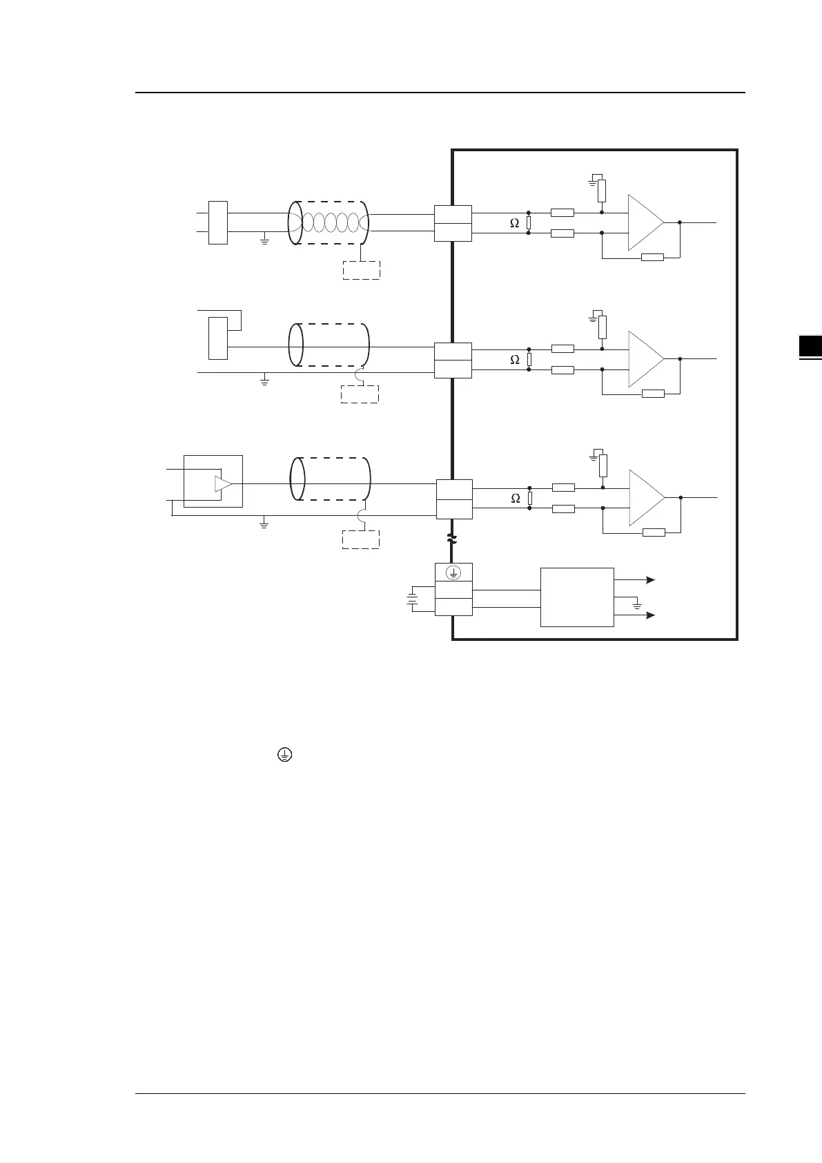
AS08AD-C External wiring
I2 +
I2 -
2 50
0V
2 4V
2 4 VD C
+ 1 5V
-1 5V
AG
*3
-2 0m A~ + 2 0m A
I1 +
I1 -
1 M
AG
1 M
* 2
FE
+
-
+
-
+ 2 4V
0V
4m A~ + 20 m A
-20 mA ~ +2 0 mA
+2 4 V
+
-
I 3+
I3 -
* 2
FE
* 2
FE
+ 24 V
0 V
0 V
C H X
* 4
C H X
* 4
CH X
*4
2 50
2 5 0
1 M
AG
1 M
2 5 0
25 0
1 M
A G
1M
25 0
Sh ield ed cab le 1*
Sh ield ed cab le 1*
Sh ield ed cab le 1*
4 w ire cu rren t in pu t-
2 w ire cur re nt in pu t-
3 w ire cu rren t inp ut-
D C /D C
C on ve rt e r
*1. Use shielded cables to isolate the analog input signal cable from other power cables.
*2. Connect the shielded cable to the terminal FE.
*3. Connect the terminal to the ground terminal.
*4. Every channel can operate with the wiring presented above.
 Loading...