ASDA-B2 Chapter 6 Control Modes of Operation
Revision May, 2018 6-21
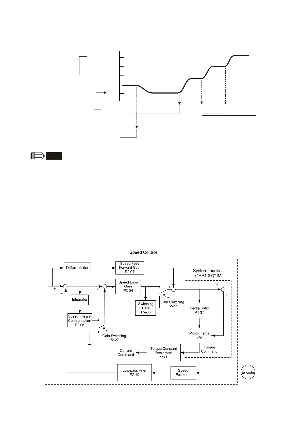
6.3.5 Timing Diagram in Speed Mode
S4 (P1-11)
S3 (P1-10)
S2 (P1-09)
S1
SPD0
SPD1
SON
OFF
ON
OFF
ON
ON
OFF
ON
Internal speed
command
External analog
voltage or zero (0)
External I/O signal
NOTE
(1) OFF means the contact point is open while ON means the contact
point is close.
(2) When it is in Sz mode, the speed command S1 = 0; When it is in S
mode, the speed command S1 is the external analog voltage input.
(3) When the servo drive is On, please select the command according
to SPD0 ~ SPD1 status.
6.3.6 Gain Adjustment of Speed Loop
Here introduces the function of speed control unit. The following shows its structure.

 Loading...


