Chapter 3 Wiring ASDA-B2
3-38 Revision May, 2018
3.6 Analog Monitor Output Connector - CN5
Analog Monitor Output Connector CN5 is used to monitor the motor operation status.
Motor characteristics such as speed and current can be represented by analog voltages.
The drive provides two channels which can be configured with the parameter P0-03 to
output the desired characteristics. Output voltage is reference to the power ground (GND).
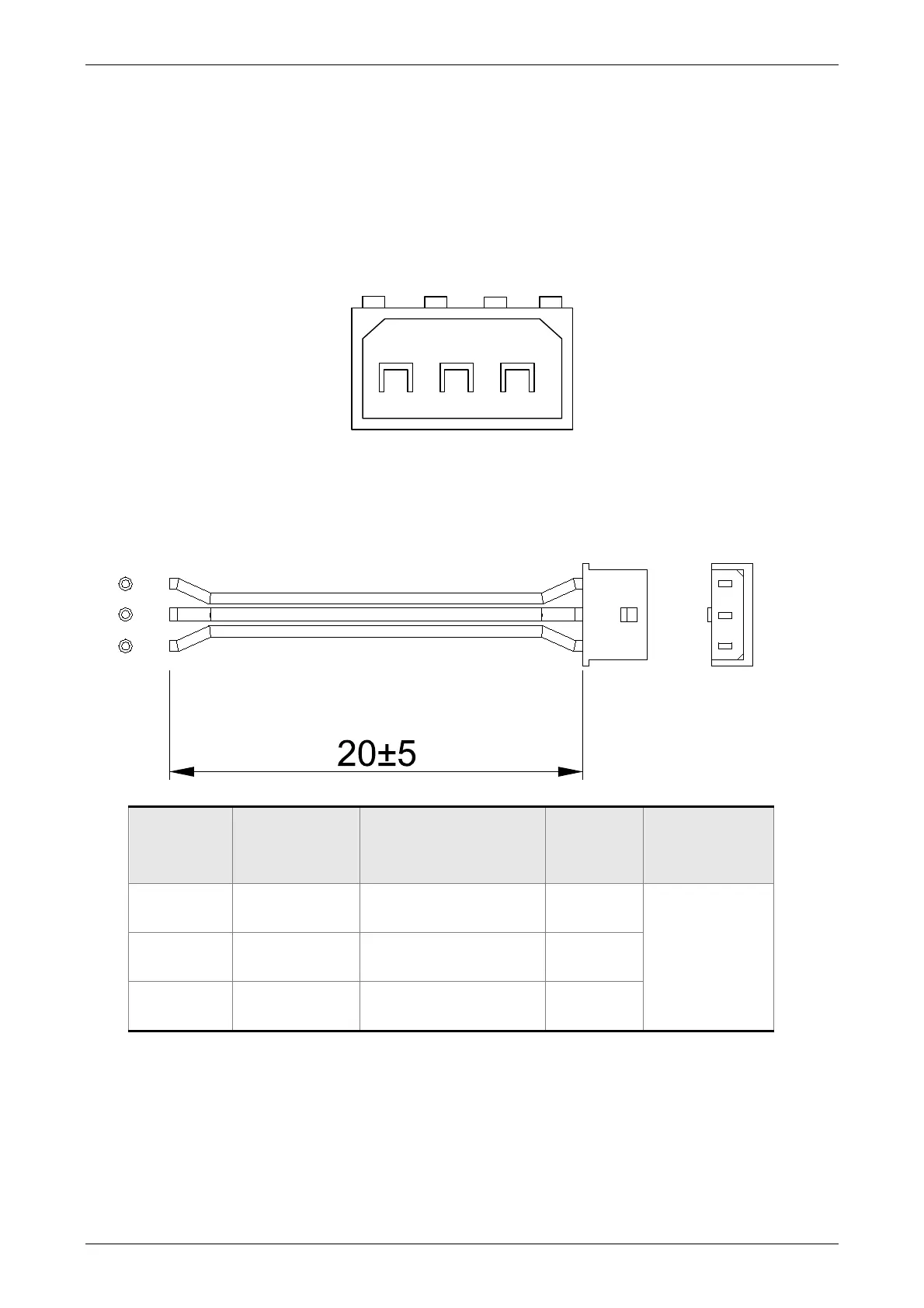
CN5 Terminal Layout and Identification
123
CN5
Signal Cable for CN5 Connector
1
2
3
PIN No. Signal Symbol
Function and
Description
Color
Wiring
Diagram
(Refer to 3.3.3)
1 MON1 Monitor analog data 1 Red
C2 2 GND Ground White
3 MON2 Monitor analog data 2 Black

 Loading...


