5. Sequential Function Chart
5.3 The Operation of STL Program
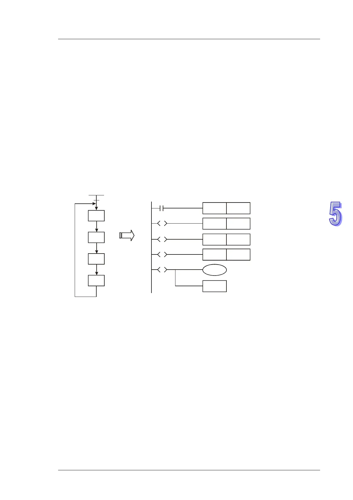
Step ladder diagram (STL) is a programming method for users to write a program which functions
similar to SFC. STL provides PLC program designers a more readable and clear programming
method as drawing a flow chart. The sequences or steps in the below SFC is quite understandable
and can be translated into the ladder diagram opposite.
STL program starts with STL instruction and ends with RET instruction. STL Sn constructs a step
point. When STL instruction appears in the program, the main program will enter a step ladder
status controlled by steps. RET instruction indicates the end of a step ladder program starting from
initial steps S0 ~ S9 and every initial step requires a RET instruction as an end of STL program.
If there is no RET instruction at the end of a step sequence, errors will be detected by WPLSoft.
S0
S21
S22
S2
3
M1002
S0
SET
SET S22
S0
RET
S21
S
S22
S
SET
S21
S0
S
S23
S
SET S23
M1002
primary pulse
Actions of Step Points:
STL program is composed of many step points, and each step point represents a single task in the
STL control process. To perform a sequential control result, every step point needs to do 3 actions.
1. Drive output coils
2. Designate the transition condition
3. Designate which step will take over the control from the current step