VFD-B Series
DELTA ELECTRONICS, INC. ALL RIGHTS RESERVED
3-2
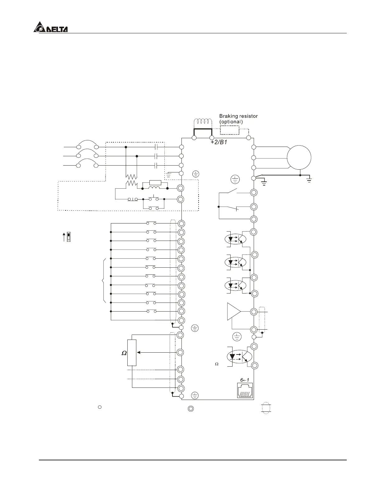
3.1 Basic Wiring Diagram
Users must connect wires according to the following circuit diagram shown below. Do not
plug a Modem or telephone line to the RS-485 communication port, permanent damage may
result. Terminals 1 & 2 are the power sources only for the optional copy keypad and should
not be used while using RS-485 communication.
AVI
ACI
AUI
ACM
B2
4~20mA
-10~+10V
+10V
5K
3
2
1
Figure 1 for models of VFD-B Series
FD007B21A/23A/43A, VFD015B21A/21B/23A/23B/43A
VFD022B23B/43B
Jumper
Power supply
+10V 20mA
Master Frequency
0 to 10V 47K
Analog Signal Common
DC choke
(optional)
E
Main circuit (power) terminals
Control circuit terminals
Shielded leads & Cable
FWD
REV
JOG
EF
MI1
MI2
MI3
MI4
MI6
TRG
MI5
DCM
+24V
Sw1
Sink
Source
Factory Default:
SINK Mode
FWD/STOP
REV/STOP
JOG
E.F.
Multi-step 1
Multi-step 2
Multi-step 3
Multi-step 4
RESET
Accel/Decel prohibit
Counter
Digital Signal Common
Factory
default
* Don't apply the mains voltage directly
to above terminals.
E
Please refer to Figure 4
for wiring of SINK
mode and SOURCE
mode.
R(L1)
S(L2)
T(L3)
Fuse/NFB(None Fuse Breaker)
SA
OFF
ON
MC
MC
RB
RC
+1
Recommended Circuit
when power supply
is turned OFF by a
fault output
R(L1)
S(L2)
T(L3)
E
Analog Multi-function Output
Te r mi n al
Factory default: Analog freq.
/ current meter
0~10VDC/2mA
U(T1)
V(T2)
W(T3)
IM
3~
MO1
MO2
MO3
AFM
ACM
RA
RB
RC
MCM
RS-485
Motor
Factory default:
indicates during operation
48V50mA
Factory default:
Freq. Setting Indication
Factory default:
Low-voltage Indication
Multi-function
Photocoulper Output
Analog Signal common
Serial interface
1: EV 2: GND
5:NC
6: for communication
3: SG-
4: SG+
DFM
DCM
Digital Frequency Output
Te r min al
Factory default: 1:1
Duty=50%
Digital Signal Common
48V50mA
48V50mA
E
E
Please refer to “Control
Terminal Explanation”.
 Loading...