5
VFD-B Series
DELTA ELECTRONICS, INC. ALL RIGHTS RESERVED
5-19
03 - 10
Desired Frequency Attained 2
Factory Setting: 0.00
Settings 0.00 to 400.00 Hz Unit: 0.01
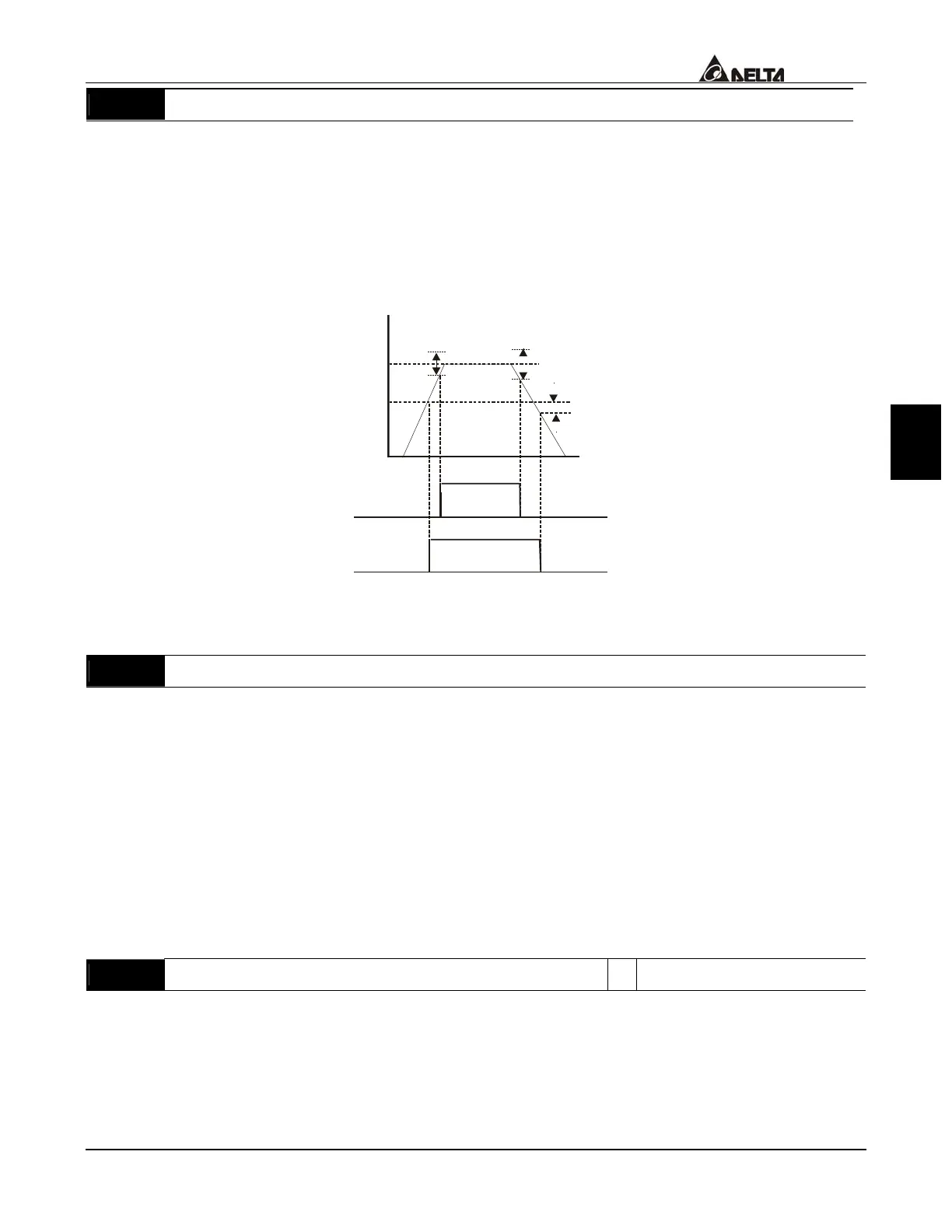
If a Multi-function output terminal is set to function as Desired Frequency Attained 1
(Pr.03-00 to Pr.03-03 = 09), then the output will be activated when the programmed
frequency is attained.
Desired Freq. 1
Detection
range
-2Hz
Detection range
+
-
4Hz
Detection range
+
-
2Hz
Time
Freq.
Max. Output
Freq.
03-04
ON
ON
OFF
OFF
OFF
OFF
Max. Freq.
Attained
Indication
03-00 to 03-03
Desired Freq.
Attained 1
Indication
03-00 to 03-03
Desired Freq. Attained 1 & Max. Freq. Attained
03 - 05
Analog Output Signal (AFM)
Factory Setting: 00
Settings 00 Analog Frequency Meter (from 0 to the Maximum Output
Frequency)
01 Analog Current Meter (from 0 to 250% of the rated AC drive
current)
02 Output voltage (from 0 to Pr.01-02)
03 Output frequency command (from 0 to the Maximum Frequency)
04 Output motor speed (from 0 to the Maximum Frequency)
05
Load power factor (cosθ = 90
o
to cosθ = 0
o
)
This parameter determines the meaning of the 0~+10VDC output from AFM and ACM.
03 - 06
Analog Output Gain
a
Factory Setting: 100
Settings 01 to 200% Unit: 1%
This parameter sets the voltage range of the analog output signal.
 Loading...