Chapter 2 InstallationC2000-HS
2-5
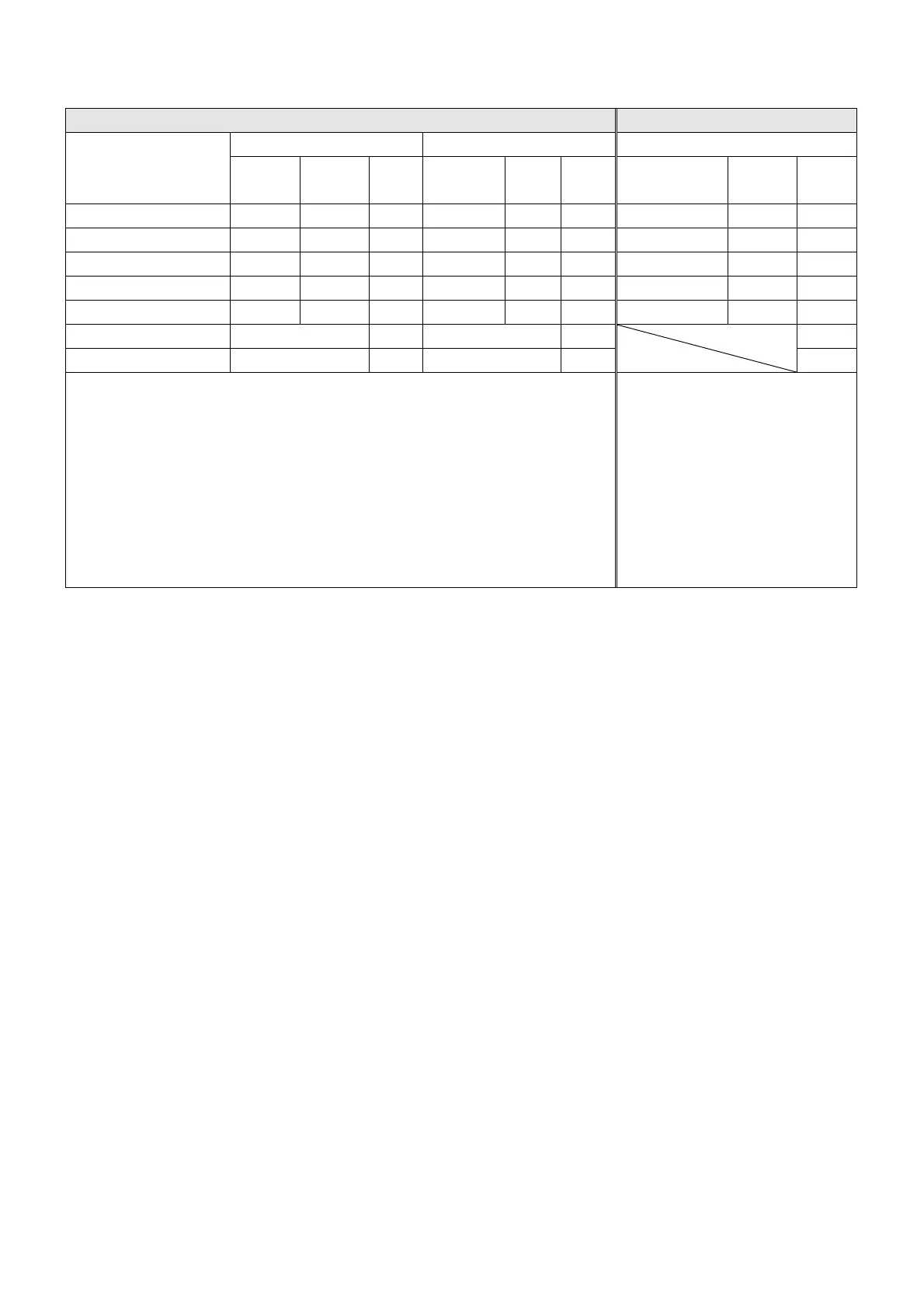
2-2 Flow and Power Dissipation
Air flow rate for cooling Power Dissipation
Model No.
Flow Rate [cfm] Flow Rate [m
3
/hr] Power Dissipation [W]
External Internal Total External Internal Total
Loss External
(Heat sink)
Internal Total
VFD300C43S-HS 148 32 180 251 55 306 TBD TBD TBD
VFD370C43S-HS 148 32 180 251 55 306 TBD TBD TBD
VFD750C43A-HS 188 32 220 319 55 374 1408 334 1742
VFD1100C43A-HS 327 80 407 556 137 692 2107 491 2599
VFD1600C43A-HS 316 199 515 537 339 875 3096 687 3783
VFD2200C43A-HS 619 619 1051 1051 5772
VFD3550C43A-HS 1042 1042 1770 1770 8007
※ The required airflow shown in chart is for installing single drive in a confined
space.
※ When installing multiple drives, the required air volume should be the
required air volume for single drive X the number of the drives
※ The heat dissipation shown in
the chart is for installing single
drive in a confined space.
※ When installing the multiple
drives, volume of heat
dissipation should be the heat
dissipated for single drive X
the number of the drives.
※ Heat dissipation for each
model is calculated by rated
voltage, current and default
carrier.
 Loading...