SEMICONDUCTORS
Only major semiconductors are shown, general semiconductors etc. are omitted to list.
The semiconductor which described a detailed drawing in a schematic diagram are omitted to list.
1. IC's
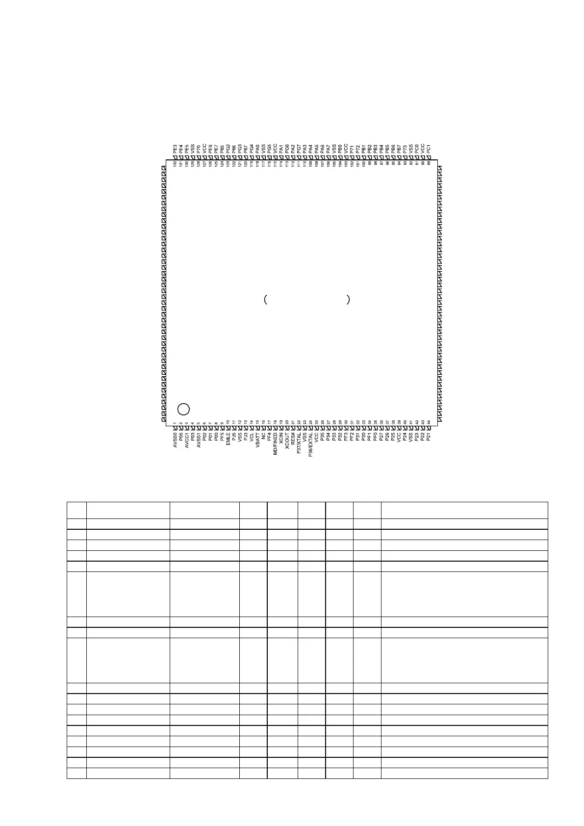
R5F56108VNFP (DIGITAL : IC151)
Terminal Functions
Pin Pin Name Symbol
I/O Pu/Pd STBY STOP
CEC
STBY
Function
1
AVSS0 AVSS0
- - - -
GND
2
P05/IRQ13 POWER KEY
I M3VPu I I I
POWER KEY (Waiting Mode cancel, interrupt port)
3
AVCC1 AVCC1
- - - -
POWER pin
4
P03/IRQ11 RED LED
O L/H L H
POWER/STANDBY LED control pin (ON:H)
5
AVSS1 AVSS1
- - - -
GND
6
P02/SCK6/IRQ10/AN120
REMOTE
POWER(232C)
(X2200(NA))/
NC(X2100(EU/CH/
AP/JP)/S910)
O L L L
232C POWER SUPPLY (REMOTE 3.3V) control pin.
(ON: H)
7
P01/RXD6/IRQ9/AN119 RXD MI232O
I Pd I I I
Data received from the external pin(AMX)
8
P00/TXD6/IRQ8/AN118 TXD MO232I
O L L L
Data transfer to external pin(AMX)
9
PF5/IRQ4
WHITE
LED(X2200(NA))/
GREEN
LED(X2200(EU/CH/
JP)/S910)
O L L L
POWER LED control pin(ON:H)
10
EMLE NC
I Pd - - -
Unused
11
PJ5 VSEL A
I I I I
Master Volume rotation detection pin(Rotary encoder)
12
VSS VSS
- - - -
GND
13
PJ3 VSEL B
I I I I
Master Volume rotation detection pin(Rotary encoder)
14
VCL VCL
I - - -
Smoothing capacitor connection pin
15
VBATT VBATT
- - - -
POWER pin
16
NC NC
I Pd - - -
NC(Pull down)
17
TRST#/PF4 NC
I/I Pd I/I I/I I/I
Unused
18
MD/FINED NC
I M3VPu I I I
Unused
88
87
86
85
84
83
82
81
80
79
78
77
76
75
74
73
72
71
70
69
68
67
66
65
64
63
62
61
60
59
58
57
56
55
54
53
52
51
50
49
48
47
46
45
133
134
135
136
137
138
139
140
141
142
143
144
145
146
147
148
149
150
151
152
153
154
155
156
157
158
159
160
161
162
163
164
165
166
167
168
169
170
171
172
173
174
175
176
PE0
P64
P63
P62
P61
VSS
P60
VCC
PD7
PG1
PD6
PG0
PD4
P97
PD3
VSS
P96
VCC
PD2
P95
PD1
P94
PD0
P93
P91
P90
P47
P45
P43
P41
P40
P07
PE1
PD5
AVCC0
P20
PE2
P17
P87
P16
P86
P15
P14
P13
P12
VCC_USB
USB0_DM
USB0_DP
VSS_USB
AVCC_USBA
USBA_RREF
AVSS_USBA
PVSS_USBA
VSS2_USBA
USBA_DP
VSS1_USBA
P83
PC7
PC6
PC5
P82
P81
P80
PC4
PC3
P77
USBA_DM
VCC_USBA
P11
P10
P53
P52
P51
P50
VSS
VCC
P76
PC2
P75
P74
P92
VSS
VCC
P46
P44
P42
VREFH0
VREFL0
RX64M GROUP
PLQP0176KB-A
176 pin LQFP
(Top View)
161
 Loading...