DigitAx User Guide
Issue code: dgxu4
4-6
4.8 Installing an external DC
braking resistor
When an external braking resistor is to be installed,
it should be installed in accordance with the
manufacturer’s instructions. Refer to Calculating the
braking resistor value in Chapter 5 Electrical Installation.
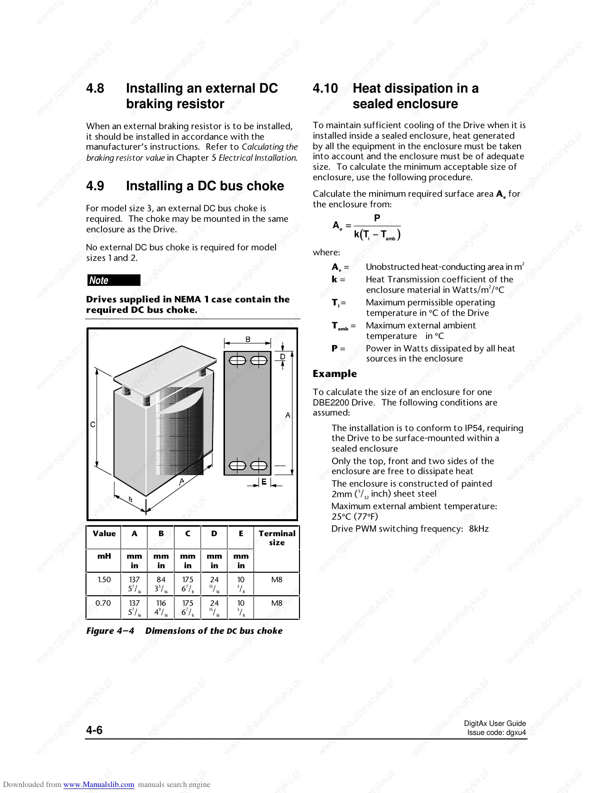
4.9 Installing a DC bus choke
For model size 3, an external DC bus choke is
required. The choke may be mounted in the same
enclosure as the Drive.
No external DC bus choke is required for model
sizes 1 and 2.
Note
Drives supplied in NEMA 1 case contain the
required DC bus choke.
Value A B C D E Terminal
size
mH mm
in
mm
in
mm
in
mm
in
mm
in
1.50 137
5
7
/
16
84
3
5
/
16
175
6
7
/
8
24
15
/
16
10
3
/
8
M8
0.70 137
5
7
/
16
116
4
9
/
16
175
6
7
/
8
24
15
/
16
10
3
/
8
M8
Figure 4–4 Dimensions of the DC bus choke
4.10 Heat dissipation in a
sealed enclosure
To maintain sufficient cooling of the Drive when it is
installed inside a sealed enclosure, heat generated
by all the equipment in the enclosure must be taken
into account and the enclosure must be of adequate
size. To calculate the minimum acceptable size of
enclosure, use the following procedure.
Calculate the minimum required surface area A
e
for
the enclosure from:
(())
A
P
kT T
e
iamb
==
−−
where:
A
ee
= Unobstructed heat-conducting area in m
2
k = Heat Transmission coefficient of the
enclosure material in Watts/m
2
/°C
T
i
= Maximum permissible operating
temperature in °C of the Drive
T
amb
= Maximum external ambient
temperature in °C
P = Power in Watts dissipated by all heat
sources in the enclosure
Example
To calculate the size of an enclosure for one
DBE2200 Drive. The following conditions are
assumed:
The installation is to conform to IP54, requiring
the Drive to be surface-mounted within a
sealed enclosure
Only the top, front and two sides of the
enclosure are free to dissipate heat
The enclosure is constructed of painted
2mm (
3
/
32
inch) sheet steel
Maximum external ambient temperature:
25°C (77°F)
Drive PWM switching frequency: 8kHz

 Loading...