DigitAx User Guide
Issue code: dgxu4
10-11
10.13 Programmable outputs
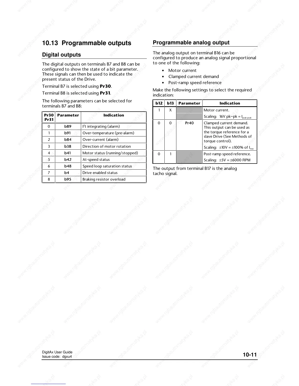
Digital outputs
The digital outputs on terminals B7 and B8 can be
configured to show the state of a bit parameter.
These signals can then be used to indicate the
present status of the Drive.
Terminal B7 is selected using Pr30.
Terminal B8 is selected using Pr31.
The following parameters can be selected for
terminals B7 and B8:
Pr30
Pr31
Parameter Indication
0 b89b89 I
2
t integrating (alarm)
1 b91b91 Over-temperature (pre-alarm)
2 b84b84 Over-current (alarm)
3 b38b38 Direction of motor rotation
4 b41b41 Motor status (running/stopped)
5 b42b42 At-speed status
6 b48b48 Speed loop saturation status
7b4b4 Drive enabled status
8 b95b95 Braking resistor overload
Programmable analog output
The analog output on terminal B16 can be
configured to produce an analog signal proportional
to one of the following:
• Motor current
• Clamped current demand
• Post-ramp speed reference
Make the following settings to select the required
indication:
b12 b13
Clamped current demand.
This output can be used as
the torque reference for a
slave Drive (See Methods of
torque control).
Scaling: ±10V = ±100% of I
max
01 Post-ramp speed reference.
Scaling: ±5V = ±6000 RPM
The output from terminal B17 is the analog
tacho signal.

 Loading...