DigitAx User Guide
Issue code: dgxu4
A-2
V
t
V
t
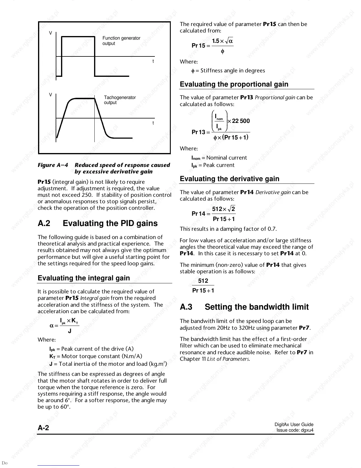
Function generator
output
Tachogenerator
output
Figure A–4 Reduced speed of response caused
by excessive derivative gain
Pr15 (integral gain) is not likely to require
adjustment. If adjustment is required, the value
must not exceed 250. If stability of position control
or anomalous responses to stop signals persist,
check the operation of the position controller.
A.2 Evaluating the PID gains
The following guide is based on a combination of
theoretical analysis and practical experience. The
results obtained may not always give the optimum
performance but will give a useful starting point for
the settings required for the speed loop gains.
Evaluating the integral gain
It is possible to calculate the required value of
parameter Pr15 Integral gain from the required
acceleration and the stiffness of the system. The
acceleration can be calculated from:
αα==
××IK
J
pk T
Where:
I
pk
= Peak current of the drive (A)
K
T
= Motor torque constant (N.m/A)
J = Total inertia of the motor and load (kg.m
2
)
The stiffness can be expressed as degrees of angle
that the motor shaft rotates in order to deliver full
torque when the torque reference is zero. For
systems requiring a stiff response, the angle would
be around 6
°
. For a softer response, the angle may
be up to 60
°
.
The required value of parameter Pr15 can then be
calculated from:
Pr
.
15
15
==
××αα
φφ
Where:
φφ = Stiffness angle in degrees
Evaluating the proportional gain
The value of parameter Pr13 Proportional gain can be
calculated as follows:
(())
Pr
Pr
13
22 500
15 1
==
××
××++
I
I
nom
pk
φφ
Where:
I
nom
= Nominal current
I
pk
= Peak current
Evaluating the derivative gain
The value of parameter Pr14 Derivative gain can be
calculated as follows:
Pr
Pr
14
512 2
15 1
==
××
++
This results in a damping factor of 0.7.
For low values of acceleration and/or large stiffness
angles the theoretical value may exceed the range of
Pr14. In this case it is necessary to set Pr14 at 0.
The minimum (non-zero) value of Pr14 that gives
stable operation is as follows:
512
15 1Pr ++
A.3 Setting the bandwidth limit
The bandwith limit of the speed loop can be
adjusted from 20Hz to 320Hz using parameter Pr7.
The bandwidth limit has the effect of a first-order
filter which can be used to eliminate mechanical
resonance and reduce audible noise. Refer to Pr7 in
Chapter 11 List of Parameters.

 Loading...