DigitAx User Guide
Issue code: dgxu4
5-3
Note
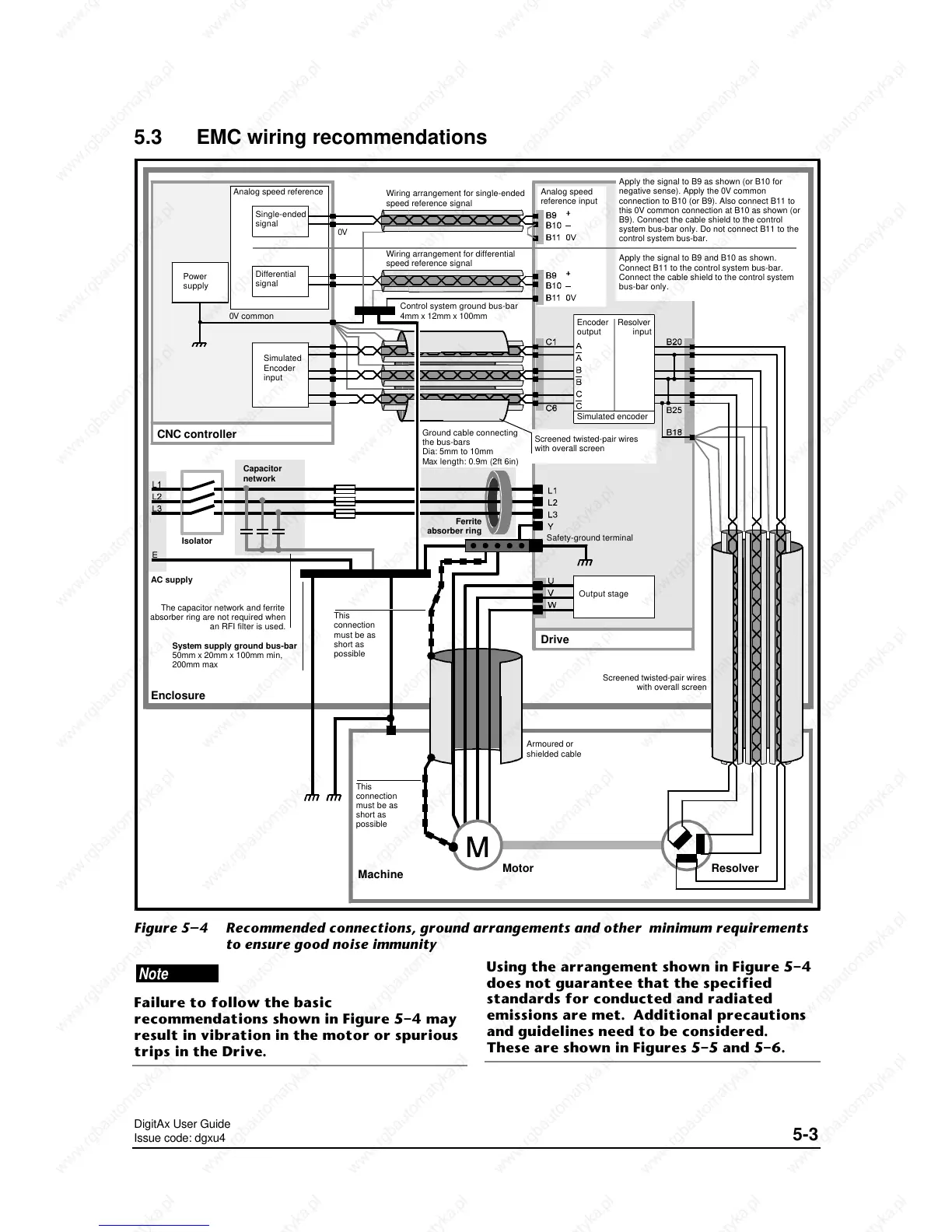
Failure to follow the basic
recommendations shown in Figure 5–4 may
result in vibration in the motor or spurious
trips in the Drive.
Using the arrangement shown in Figure 5–4
does not guarantee that the specified
standards for conducted and radiated
emissions are met. Additional precautions
and guidelines need to be considered.
These are shown in Figures 5–5 and 5–6.
5.3 EMC wiring recommendations
Power
supply
Analog speed reference
Simulated
Encoder
input
0V common
CNC controller
Control system ground bus-bar
4mm x 12mm x 100mm
Encoder
output
Resolver
input
ResolverMotor
Enclosure
Drive
Ground cable connecting
the bus-bars
Dia: 5mm to 10mm
Max length: 0.9m (2ft 6in)
Safety-ground terminal
Ferrite
absorber ring
Capacitor
network
Isolator
AC supply
Machine
System supply ground bus-bar
50mm x 20mm x 100mm min,
200mm max
Screened twisted-pair wires
with overall screen
Armoured or
shielded cable
Screened twisted-pair wires
with overall screen
Output stage
Simulated encoder
This
connection
must be as
short as
possible
This
connection
must be as
short as
possible
The capacitor network and ferrite
absorber ring are not required when
an RFI filter is used.
Wiring arrangement for differential
speed reference signal
Single-ended
signal
Analog speed
reference input
Wiring arrangement for single-ended
speed reference signal
Differential
signal
Apply the signal to B9 as shown (or B10 for
negative sense). Apply the 0V common
connection to B10 (or B9). Also connect B11 to
this 0V common connection at B10 as shown (or
B9). Connect the cable shield to the control
system bus-bar only. Do not connect B11 to the
control system bus-bar.
Apply the signal to B9 and B10 as shown.
Connect B11 to the control system bus-bar.
Connect the cable shield to the control system
bus-bar only.
0V
Figure 5–4 Recommended connections, ground arrangements and other minimum requirements
to ensure good noise immunity

 Loading...