12
Megohmmeter / Cable Insulation Integrity Check
1. Separate EQD’s and disconnect the Tray Cable wires from the Alarm Panel.
2. Using a 500V Megohm meter, check for shorts between all wires.
3. If shorts are found, remove the EQD insert from the cable and perform test again.
4. If shorts go away, then replace the insert and perform test again.
5. If shorts do not go away then the Tray Cable will need to be replaced.
Amperage Checks
The use of a clamp on amp meter can be helpful in identifying problems such as a
restricted/blocked discharge line, blown Stator, faulty Check/Anti-siphon valve, etc...
1. Set the clamp-on amp meter to the appropriate scale.
2. Hook the probe around the Black power lead in the alarm panel.
3. With the power on, fill the tank until the pump operates, or depress the push to run
switch in the panel.
4. Read the current directly. Refer to the following table for troubleshooting.
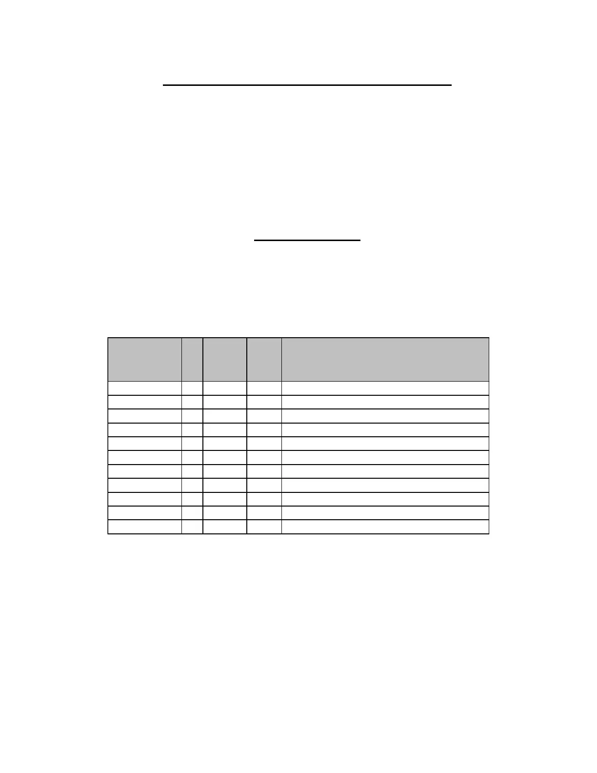
Table 3 – 6
The figures shown are averages and meant to be used for approximation since motors, voltages
and amp meters vary. The table displays a comparison of back pressure (psi), flow (GPM),
current draw (amperes) and head (feet of water pressure). By knowing the current draw, you
may discover a restricted or blocked discharge line, blown pump Stator, high head operation,
etc.
A jammed grinder may trip the circuit breaker or cause the overload protector to cycle. This
causes the pump to cycle on and off, and eventually results in an alarm condition. A torn or
worn out pump Stator results in a “runs but does not pump” condition and eventually, as the
water rises, causes an alarm. Replace the Stator and, if necessary, the Rotor.
GPM Comments
4.9 (9.8) or less 0 0 0 Worn Stator
5.6 (11.2) 10 24 14 Normal
5.8 (11.6) 20 46 13 Normal
6 (12) 30 70 12 Normal
6.2 (12.4) 40 92 11 Normal
6.5 (13) 50 115 10 Normal
6.8 (13.6) 60 138 9 Normal
7.1 (14.2) 70 161 8 Normal
7.4 (14.8) 80 184 7.5 Normal
90+ 207+ varies
Plugged Discharge Line or bad bearings
over 15 (30) 0 0 0
Jammed Grinder or Shorted Motor
 Loading...

