64
Motor Windings Test
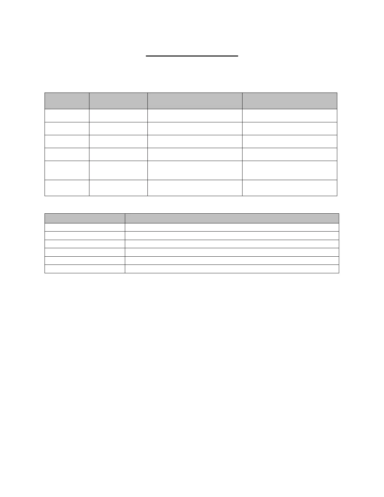
1. Perform motor winding resistance check per chart below to verify motor condition.
Franklin Motor Field Winding Resistance
Any reading; possibly water in
motor. Dry windings and retest
Table 10 – 1
Run/Start windings and internal thermal protector
Jumper lead (120V units Only)
Table 10 – 2
Note: While you have all of the wires disconnected between the Control Bracket, the Power
Cable, and the Transceiver Board, replace the two O-rings on the Motor Casting before you
rewire the Controls. Use Molycote 55 Grease on the Motor Housing and Motor Head O-rings.
Use Silicon Grease on all other O-rings
Control Bracket Installation
1. Plug the yellow wire into terminal 1 on the start switch.
2. Plug the grey wire into terminal 3 on the start switch.
3. Insert the blue wire into 2/T1 on the contactor and tighten.
4. Set the Control Bracket into the control cavity and secure it with the two screws. (Note:
Install the power cable ground wire with the screw on the thermal protector side of the
Control Bracket)
5. Insert the red wire from the Power Cable into 1/L1 on the contactor and tighten.
6. Insert the red wire from the Transceiver Board into 3/L2 on the contactor and tighten.
7. Insert the black wire from the NC-8 crimp wire nut connector and the black wire from the
thermal protector into A1 of the contactor and tighten.
8. Insert the brown wire from the Power Cable and the brown wire from the Transceiver
Board into A2 on the contactor and tighten.
9. Using a butt splice, connect the black motor wire to the black thermal protector wire.
 Loading...

