66
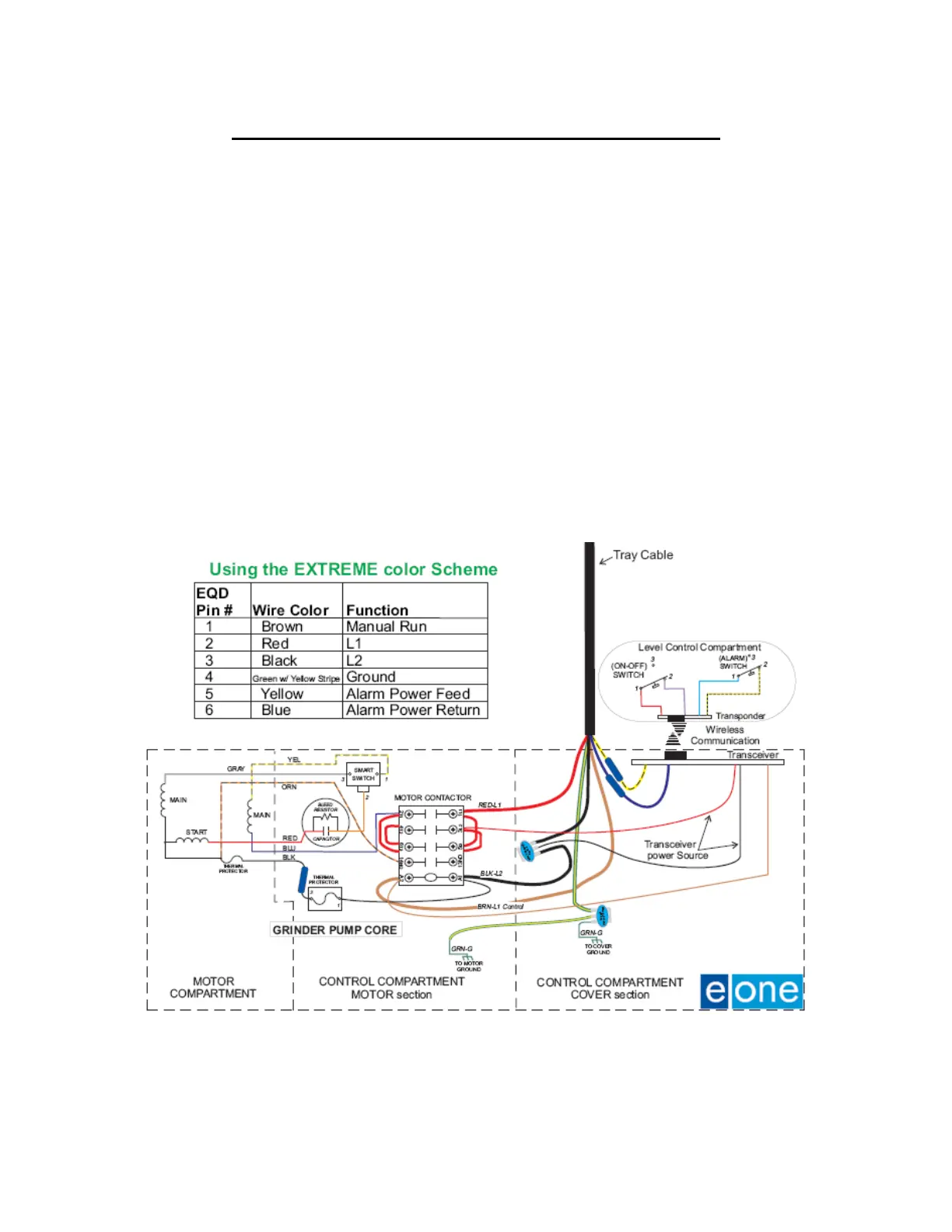
Transceiver Board & Control Bracket Wiring
Note: Refer to the wiring diagram on the following page for these wiring instructions.
1. Using Butt Splices connect the yellow and blue wires from the Power Cable to the
Transceiver Board. Bundle both sets wires together with a wire tie.
2. Using a NC-8 crimp wire nut electrical connector, connect the three green ground wires
together and bundle them together with a wire tie.
3. Connect the red wire from the Transceiver Board to terminal 3/L2 on the contactor.
4. Connect the brown wire from the Transceiver Board and the brown wire from the Power
Cable to terminal A2 on the contactor.
5. Using a NC-8 crimp wire nut electrical connector, connect the black wire from the
Transceiver Board, the black wire from the Power Cable and the black wire from terminal
A1 of the contactor together and bundle them together with a wire tie.
6. Connect the red wire from the Power Cable to terminal 1/L1 of the contactor.
 Loading...

