53
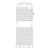
3. Lubricate (Dow 111 grease) both O-rings on both pressure switches.
Figure 9 – 10
4. Connect the red wire to terminal 1 and the brown wire to terminal 2 of the On/Off switch.
5. Align the electrical spade connectors opposite of the Transponder Board in order to
install the On/Off switch into the Level Sensor.
6. Push the On/Off Switch into the Level Sensor and install the Pressure Switch Retainer
on the opposite side of the wires aligning the slots with the tabs.
7. Install one new main Level Sensor molded radial seal into the molded tongue of the
On/Off Switch side of the Level Sensor and lubricate the exposed surface after
installation (Silicone Grease).
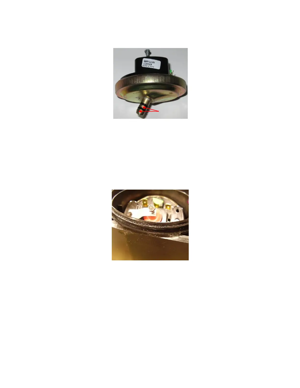
Figure 9 – 11
8. Connect the yellow wire to terminal 1 and the blue wire to terminal 2 of the Alarm Switch.
9. Push the Alarm Switch into the Level Sensor and install the Pressure Switch Retainer on
the opposite side of the wires aligning the slots with the tabs.
10. Assemble the two halves of the assembly using caution not to pinch any wires
11. Re-install all four screws into the Level Sensor and tighten them in an X pattern. (Note:
longer screws in the bottom) Use caution not to over tighten the screws.
 Loading...

