Communications
Communication ports
The Form 4D control has a front panel configuration
data port and provisions for two optional side-panel
communication ports (Figure 10).
The front panel configuration data port is described in the
Operating Panel section of this manual.
There are two standard USB ports (one host and one client),
as well as any two of the following: RS-232, RS-485, Serial
fiber, Ethernet wire, Ethernet fiber (MTRJ Multi-mode, SC
Multi-mode, ST Multi-mode, and LC Single-mode).
Communication protocols
Seven native communication protocols are available for the
Form 4D recloser control:
Serial protocols
DNP3
2179
MODBUS
IEC 60870-5-101
Ethernet protocols
DNP3 TCP/IP
MODBUS TCP/IP
IEC 70870-5-104
Any available communication protocol can be selected
and configured by the user with the ProView NXG
applicationsoftware.
DNP3 is factory-defaulted to the communication ports on
the side panel.
Ethernet Communications
ProView NXG over TCP/IP.
DNP3 IP.
IEC60870-5-104.
Ethernet connection allows for network application of the
Form 4D pole-mount control for both DNP3 and ProView
NXG protocols. In addition, the front panel data port can
simultaneously communicate ProView NXG to the PC.
Ethernet configuration is accomplished via ProView NXG
interface software. Refer to S280-104-2 Form 4D Control
Programming Guide for Ethernet Configuration information.
The user can simultaneously communicate to the Form
4D control using both the front panel data port and the
appropriate side panel communication port.
Control information
Control information includes firmware identification by
catalog number and name, date code, and ProView NXG
release number. Control information is available through the
NAMEPLATE DATA menu on the front panel (Figure 4).
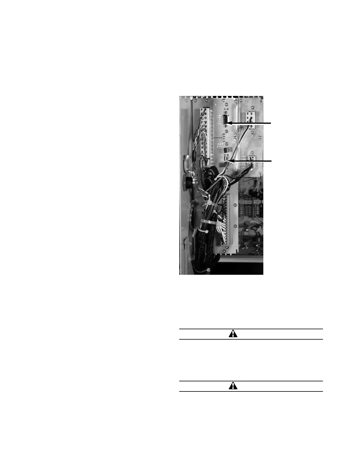
Control side panel
The control side panel is easily accessible when the swing-
panel of the control cabinet is opened.
Port 1:
RS-232 Serial
Communications
option
Port 2:
Serial Fiber, ST
Communica-
tions
Figure 10. Form 4D Pole-mount recloser control
communication port identification
Installation procedure
Initial programming prior to installation
CAUTION
Equipment misoperation. Do not connect this control
to an energized recloser until all control settings have
been properly programmed and verified. Refer to the
programming information for this control. Failure to
comply can result in control and recloser misoperation,
equipment damage, and personal injury.
G110.3
CAUTION
Loss of protection. Reconfigure the user settings. When
the CONTROL OK LED is flashing, control protection
is disabled. User protection profile settings must be
reconfigured to enable protection. Loss of protection can
result in personal injury and equipment damage.
T360.1
12 OPERATION INSTRUCTIONS MN280049EN September 2017
Form 4D Microprocessor-based pole-mount recloser control installation and operation instructions
 Loading...


