b. Press the down arrow button to scroll to the Test
Battery command. Press the ENTER button.
The following message will appear: 082 Test
Battery (CONFIRM).
c. Press the ENTER key. The (TESTING...) message
will appear. (The test duration is approximately
fiveseconds.)
If the battery is OK, the (PASS) message
willappear.
If the battery is not OK, one of these messages
will appear:
“ATTENTION – 1” indicates Battery Test Trouble*
“ATTENTION – 2” indicates Battery Test Failed
“ATTENTION – 3” indicates Battery Test
Currently Running
“ATTENTION – 4” indicates Battery Test
Blocked**
d. The battery test results can be viewed by pressing
the down arrow. The following information will be
displayed:
VBat = XX.XX Volts
IBat = -X.XX Amps
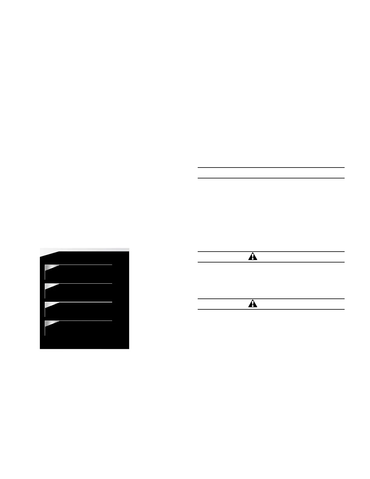
4. Verify the Control OK LED is illuminated on the control
operator panel. The AC POWER LED indicates the
presence of AC power (Figure 34).
DATA PORTS
ENTER
EDIT
ESC
PHASE FAULT
A B C
GROUND FAULT
ABOVE MIN TRIP
LOCKOUT
OPEN
CLOSED
VOLTAGE TRIP
FREQUENCY TRIP
SENSITIVE GND
A B C
X Y Z
PHASE VOLTAGE
ALARM
BATTERY
AC POWER
CONTROL OK
ALT
PROFILE 1
GND TRIP
BLOCKED
NON
RECLOSE
SUPER-
VISORY
OFF
HOT LINE
TAG
TRIP
OFF
(LOCKOUT)
CLOSE
Figure 34. Control OK and AC POWER LEDs
ote:N The control includes a Power Save feature that
will turn off the LEDs and backlit LCD display after
15minutes of inactivity at the front panel (no buttons
pressed). The CONTROL OK and HOT LINE TAG
LEDs are not affected by the power save mode.
Pressing any key on the front panel will turn the LCD
backlight on and restore all LEDs to their current on/
off states.
All other tests described in this TESTING section require the
Form 4D pole-mount recloser control to be removed from
service, connected to a bypassed recloser, or tested at a
location where the proper testing equipment is available.
Alarm Condition:
During a battery test a 5Ω, 55 watt resistor is placed
across the battery terminals for approximately 5 seconds.
The Form 4D control measures the battery voltage, if
the voltage drops below 22.8 VDC the BATTERY LED
illuminates (Figure 34) and a battery alarm is issued, if
configured, at the end of the test.
Remove the control from service
IMPORTANT
Disconnect switches for AC sensing and power
connections are necessary to isolate the Form 4D
control for testing and servicing.
1. Enable GND TRIP BLOCKED to disable the
groundelement.
ote:N This prevents the control from tripping on imbalance
as the control cable is connected and disconnected.
A. Press the GND TRIP BLOCKED button. The LED
should be illuminated.
CAUTION
Hazardous voltage. Open CT secondaries can generate
high voltages. Contact with CT pins of the disconnected
cable can cause electric shock and may result in personal
injury. Open recloser contacts and open disconnect
switches before disconnecting control cable.
T204.3
CAUTION
Hazardous voltage. Cable conductors attached to controls
will remain at 53 VDC and 120/240 VAC potential while
connected to the control. Contact with any pins at
the end of the cable directly or indirectly connected
to a control can result in personal injury or equipment
damage. Disconnect battery and external power sources
in the control then remove control cable at control end
before disconnecting from recloser end.
T312.2
2. Disconnect the 24V control battery.
3. Disconnect control cable from control.
4. Remove control AC sensing and power connections
from the control.
5. Disconnect any serial communications ports connections
(Figure 35).
6. Disconnect the ground from the control.
* Battery Test Trouble indicates that the test results were not lower than
battery failure voltage (15V) and not higher than the test voltage (22.8V).
** Battery Test Blocked indicates a battery test was attempted with battery
power only. The battery cannot be tested when the control is powered
from the battery only (no AC power).
37
OPERATION INSTRUCTIONS MN280049EN September 2017
Form 4D Microprocessor-based pole-mount recloser control installation and operation instructions
 Loading...


