The front panel LCD display is used to configure the
operating settings for the control. It is also used to display
metering, counter information, control parameters, alarms,
and sequence of events.
Control parameters can also be programmed via a personal
computer connected to the control through the front
panel USB port or the communications boards. Control
programming, interrogation, and operations are performed
with Form 4D ProView NXG
TM
interface software on
acomputer.
ProView interface program software includes additional
functions used to create and graphically display Time
Current Curves, configurable sequence of events and alarm
data, and selectable communication points for serial (DNP,
Modbus, IEC 61850, 2179, IEC 60870-5-101) and Ethernet
communication
(DNP3 IP, IEC 60870-5-104).
The control operates on 50 and 60 Hz systems.
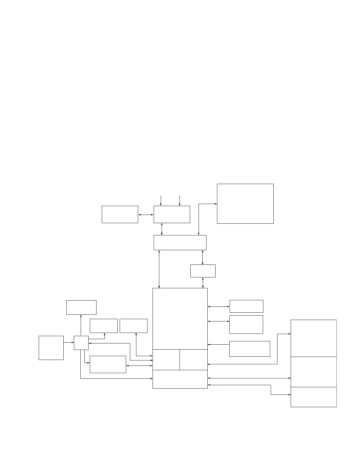
Theory of operation
A functional block diagram of the Form 4D recloser control
is shown in Figure 2. Current sensing is provided by three
current transformers located in the recloser and interfaced to
the Form 4D recloser control via the control cable. This cable
also supplies Trip, Close, and Recloser status, and provides
isolation for reliable operation. Voltages for metering are
connected to the control through the cabinet harness.
Line current flowing through the recloser is converted
to a digital signal suitable for metering and fault current
calculations. Data sampling occurs at a rate of 64 times per
cycle. The control contains a data acquisition section that
uses the acquired samples to compute the fundamental
currents and voltage for use in overcurrent, under/
overvoltage, and under/overfrequency protection, as well as
currents and voltages for metering functions. The currents
are calculated four times a cycle for overcurrent protection.
The current only includes the fundamental frequency
current and does not include harmonics or DC.
TRIP SOLENOID
CLOSE SOLENOID
A Ø CT
B Ø CT
C Ø CT
OPEN / CLOSE
SWITCHES
CT COMMON
RECLOSER
AC INPUT
POWER
BATTERY
INTERCONNECT
BOARD
I/O BOARD
FRONT
PANEL
USB CLIENT
(PROVIEW NXG)
CONNECTIONS
COMMUNICATIONS
BOARD ACCY (OPTIONAL)
•RS-232
•RS-485
•SERIAL FIBER
•ETHERNET (WIRED)
•ETHERNET (FIBER)
VOLTAGE SENSING
4 inputs
4 outputs
USB HOST
(MEMORY STICK)
DIGITAL
ANALOG BOARD
POWER
SUPPLY
RECLOSER
INTERFACE
ANALOG INPUT
SIGNAL CONDITIONING
TB1
OUTLET
ACCESSORY
I/O BOARD
OPTIONAL
ADD-ONS
AUXILIARY
POWER SUPPLY
HEATER
Figure 2. Form 4D Pole-mount recloser control operational flow diagram
3OPERATION INSTRUCTIONS MN280049EN September 2017
Form 4D Microprocessor-based pole-mount recloser control installation and operation instructions
 Loading...


