Table 14. Ethernet communication card configurations
Type Card
configurations
Output
connectors
Communication
speed
1 10/100 Base-T (wired) RJ-45 10/100MBps
(auto-switching)
2 100 Base-FX (multi-mode fiber) MT-RJ 100MBps
(full-duplex)
3 100 Base-FX (multi-mode fiber) SC 100MBps
(full-duplex)
4 100 Base-FX (multi-mode fiber) ST 100MBps
(full-duplex)
5 100 Base-FX, (single-mode fiber) LC 100MBps
(full-duplex)
Maximum link length is determined by the use of the
particular physical layer implementation, and can be further
constrained by the actual network configuration. In case of
the 100Base-FX MT-RJ connector based implementation,
maximum link length in excess of 2000m can be achieved
with 62.5/125µm multi-mode fiber. The fiber-optic link uses
1300nm wavelength, and can easily be interfaced to other
100Base-FX solutions (ST connector patch cord solution).
Table 15 indicates the pin assignments for the Ethernet
(wired) communication card accessory (Figure 32).
Table 15. Ethernet (RJ-45) communication port
pinassignments
Pin number Pin name Pin description
1 TX+ Transmit data (positive)
2 TX– Transmit data (negative)
3 RX+ Receive date (positive)
4 NC No connection
5 NC No connection
6 RX– Receive data (negative)
7 NC No connection
8 NC No connection
J2 Connector
8
7
6
5
4
3
2
1
Figure 32. Ethernet (wired) communication port
pinidentification
Testing
CAUTION
Equipment misoperation. Do not connect this control
to an energized recloser until all control settings have
been properly programmed and verified. Refer to the
programming information for this control. Failure to
comply can result in control and recloser misoperation,
equipment damage, and personal injury.
G110.3
IMPORTANT
The Form 4D control can be taken out of service for testing
and placed back into service without de-energizing its
recloser and interrupting the system. However, during the
time the control is out of service, the recloser is inoperative.
Testing an installed control
The following tests to determine initial operation of the
Form 4D pole-mount recloser control can be performed
while connected to an operating recloser.
ote:N These are the only tests performed on an installed,
operating control.
1. Verify operating status of all indicator lights by pressing
any key to reactivate the display and active LEDs.
2. Check the operational values for currents, voltages, and
other metering information.
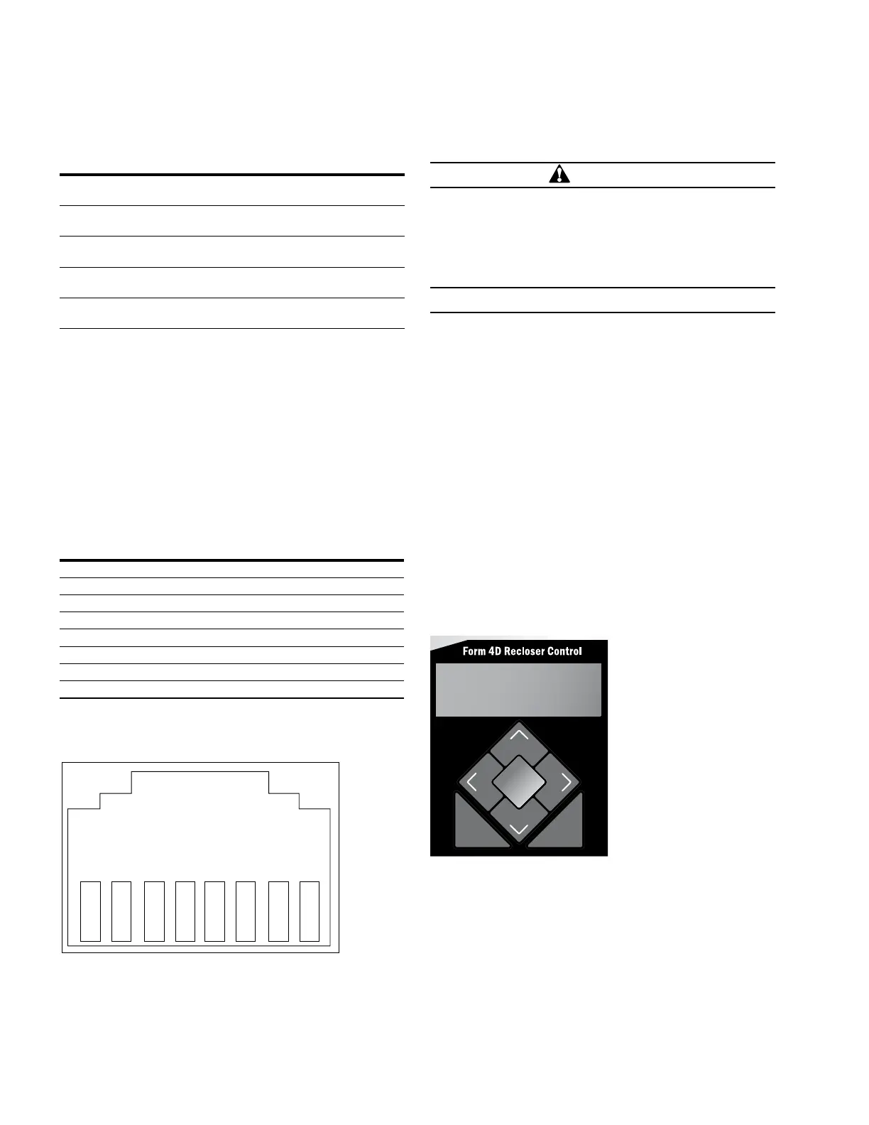
ote:N Scroll through the LCD display messages by pressing
the and cursor movement arrows underneath the
LCD display on the programming panel (Figure 33).
ENTER
EDIT
ESC
PHASE FAULT
A B C
GROUND FAULT
ABOVE MIN TRIP
LOCKOUT
OPEN
CLOSED
VOLTAGE TRIP
FREQUENCY TRIP
SENSITIVE GND
A B C
X Y Z
PHASE VOLTAGE
ALARM
BATTERY
AC POWER
CONTROL OK
ALT
PROFILE 1
GND TRIP
BLOCKED
NON
RECLOSE
SUPER-
VISORY
OFF
HOT LINE
TAG
TRIP
OFF
(LOCKOUT)
CLOSE
Figure 33. LCD display and cursor movement arrows
3. View battery information and test battery operation
asfollows:
a. Scroll down the front panel HMI to the BATTERY
menu item and press the ENTER button. Code 081
Battery Voltage and Current will be displayed:
VBat = XX.XX Volts
IBat = -X.XX Amps
36 OPERATION INSTRUCTIONS MN280049EN September 2017
Form 4D Microprocessor-based pole-mount recloser control installation and operation instructions
 Loading...


