6. Tilt back, but do not remove, the module from the
swing panel (Figure 47).
ote:N Rest the lower portion of the module on the swing
panel opening.
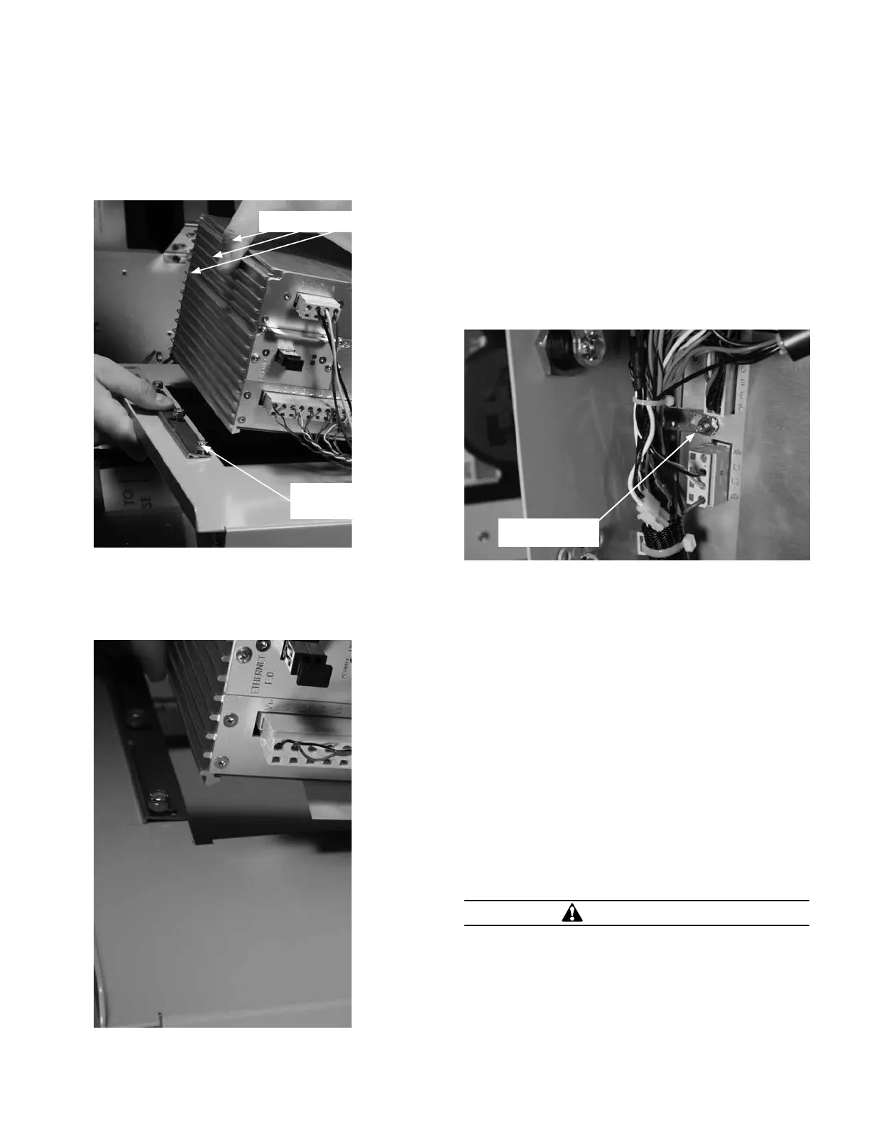
Module swing panel
ground link nuts
Three (3) retaining bar nuts
Figure 47. Loosen retaining bar nuts and tilt module back
7. Remove the existing insert(s) intended for replacement
by pulling on the tab(s) that extend out of the side of
the module (Figure 48).
Figure 48. Remove existing insert
8. Slide the new insert(s) into the module and align so the
text and LED slots are oriented in the window opening
on the front panel.
An electronic label template is included on the ProView
NXG application software CD and, once installed on your
PC, can be accessed through the following default address:
C:\Program Files\Cooper\ProView NXG\Form 4D\Form 4D
Control Customizable Inserts.doc.
Two blank label templates are included with your control.
9. Position the ground link on the swing panel to line up
with the ground lug on the module as it moves into
position (Figure 49).
Ground link nut
Figure 49. Position the ground link on the swing panel
to line up with the ground lug on the module
10. Lift up on the module until the ground link slides into
place and continue lifting up until the module is firmly
back into the swing panel.
11. Press into place as necessary.
12. Torque the nuts on the ground link to 24 in.-lbs.
(Figure 49).
13. Slide the retaining bar down all the way over the
module’s aluminum extrusion as much as possible.
14. Torque the three (3) nuts to 24 in.-lbs. (Figure 47).
15. Reconnect the battery (if used).
16. Reconnect AC input power to TB1 or to AC input
receptacle, if applicable.
1 7. Verify the module powers up properly.
Remove Existing Module
CAUTION
Equipment misoperation. The control must be removed
from service prior to performing any maintenance,
testing, or programming changes and not (re)connected
to an energized recloser until all settings have been
verified. Failure to comply can result in equipment
misoperation, equipment damage, and personal injury.
G166.0
45OPERATION INSTRUCTIONS MN280049EN September 2017
Form 4D Microprocessor-based pole-mount recloser control installation and operation instructions
 Loading...


