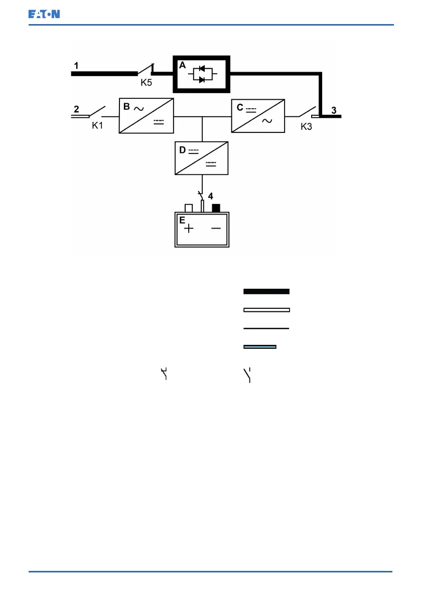
Figure 7: Path of current through the UPS in the bypass mode
A Static switch 1 Bypass input Main power flow
B Rectifier 2 Rectifier input
Energized
C Inverter 3 Output
De-energized
D Battery
converter
4 Battery breaker
Trickle current
E Battery
Closed Open
In the bypass mode, the output of the system is provided with AC power directly
from the system input. While in this mode, the output of the system is not
protected from voltage or frequency fluctuations or power outages from the
source. Some power line filtering and transient protection is provided to the load,
but no active power conditioning or battery support is available to the output of
the system in the bypass mode.
The static bypass consists of a solid-state, silicon-controlled rectifier (SCR) static
switch (STSW) and a backfeed protection isolation device K5. The static switch is
rated as a continuous-duty device that is used anytime the inverter is unable to
support the applied load. The static switch is wired in series with the backfeed
protection. As the static switch is an electronically-controlled device, it can be
turned on immediately to pick up the load from the inverter without interruption.
The backfeed protection is normally always closed, ready to support the static
switch unless the bypass input source becomes unavailable.
© Eaton Corporation plc 2020. All rights reserved. Revision: 006 Document ID: P-164000493 28 (126)
Eaton 91PS/93PS UPS 8–40 kW User’s and Installation Guide
 Loading...