5.2 Steps to install the UPS
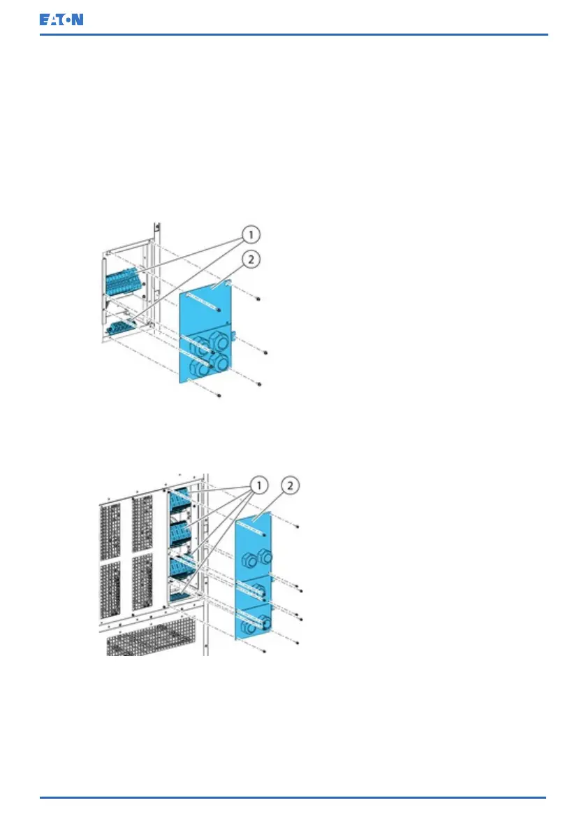
Power and control wiring are routed through the rear of the cabinet with
connections made to easily accessible terminals, see Figure 16: Gland plate and
connector locations in the 15-20 kW standard and C-model frames and Figure
17: Gland plate and connector locations in the 30-40 kW frame.
To install and connect the power cabling of the external battery to the UPS, see
Section 5.3 Battery system installation.
Figure 16: Gland plate and connector locations in the 15-20 kW standard and C-
model frames
1. Connectors 2. Gland plate
Figure 17: Gland plate and connector locations in the 30-40 kW frame
1. Connectors 2. Gland plate
© Eaton Corporation plc 2020. All rights reserved. Revision: 006 Document ID: P-164000493 61 (126)
Eaton 91PS/93PS UPS 8–40 kW User’s and Installation Guide
 Loading...