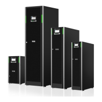
1. To gain access to the terminal blocks, remove the screws securing the gland
plate at the back of the UPS.
2. Install suitable cable glands into the gland plate.
3. Route the cables through the glands.
4. Connect the cables to the respective terminal blocks, see Figures in Section
4.4.3 UPS system power wiring preparations.
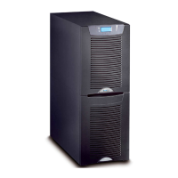
5. Route the communication cables to the front of the unit through the cable
clips at the back of the unit and through the oval hole at the top.
6. Connect the communication cables to the respective terminals and
peripherals. For detailed information, see Figures 26: Communication
interfaces in the 15/20 kW standard and C-model frames and
27: Communication interfaces in the 30/40 kW frame and Sections
5.5 Install a remote EPO switch and 5.6 Installing interface connections.
7. Assemble the internal batteries into the battery trays. Connect the battery
blocks in series within the battery tray. Only use cables specified by Eaton.
Note that the battery trays may differ from the illustration.
© Eaton Corporation plc 2020. All rights reserved. Revision: 006 Document ID: P-164000493 62 (126)
Eaton 91PS/93PS UPS 8–40 kW User’s and Installation Guide
 Loading...