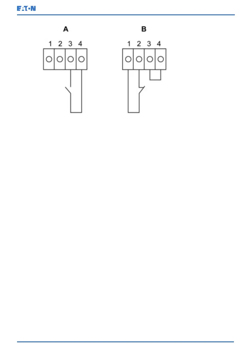
Figure 32: Connections of the relay contacts
You can use a normally-closed or normally-open contact. If the state of the
contact changes from the state you specify as normal, a signal is issued. You can
connect this contact to equipment at your facility (such as a light or an alarm bell)
to let you know when an alarm is active on the UPS. This feature is useful if the
UPS is located in a remote area where the UPS horn may not be heard
immediately.
NOTE: Do not operate the contacts in excess of 30 VAC (RMS) and 30 VDC at 5
A maximum.
6.7 Configuring relays
91PS/93PS offers one native relay output. Additionally, each of the 2 MiniSlots
can be equipped with a relay card, including 5 relays. The following instructions
guide you through the relay configuration.
Currently the relay configuration can be done only using the display. The service
tool does not yet have support for nodebit functions.
The maximum voltage of the relay is 30 V. Examine the voltage and current
specifications of the other cards from the previous sections.
The process for relay configuration:
1. In the home screen of the display, click the lock icon in the top right corner to
type in the service password.
© Eaton Corporation plc 2020. All rights reserved. Revision: 006 Document ID: P-164000493 83 (126)
Eaton 91PS/93PS UPS 8–40 kW User’s and Installation Guide
 Loading...