24 4–20kVA Users Guide P-164000669 4–20kVA Users Guide P-164000669—Rev 09
33..44 BBPPMM SSiiggnnaall IInnppuutt WWiirree RRoouuttiinngg
CAUTION
The auxiliary contacts must be wired to the BPM from the UPS for proper functionality. These auxiliary contacts
signal the UPS to go to Internal Bypass mode to provide a synchronized transfer. Failure to wire the auxiliary
contacts can be dangerous and result in system failure.
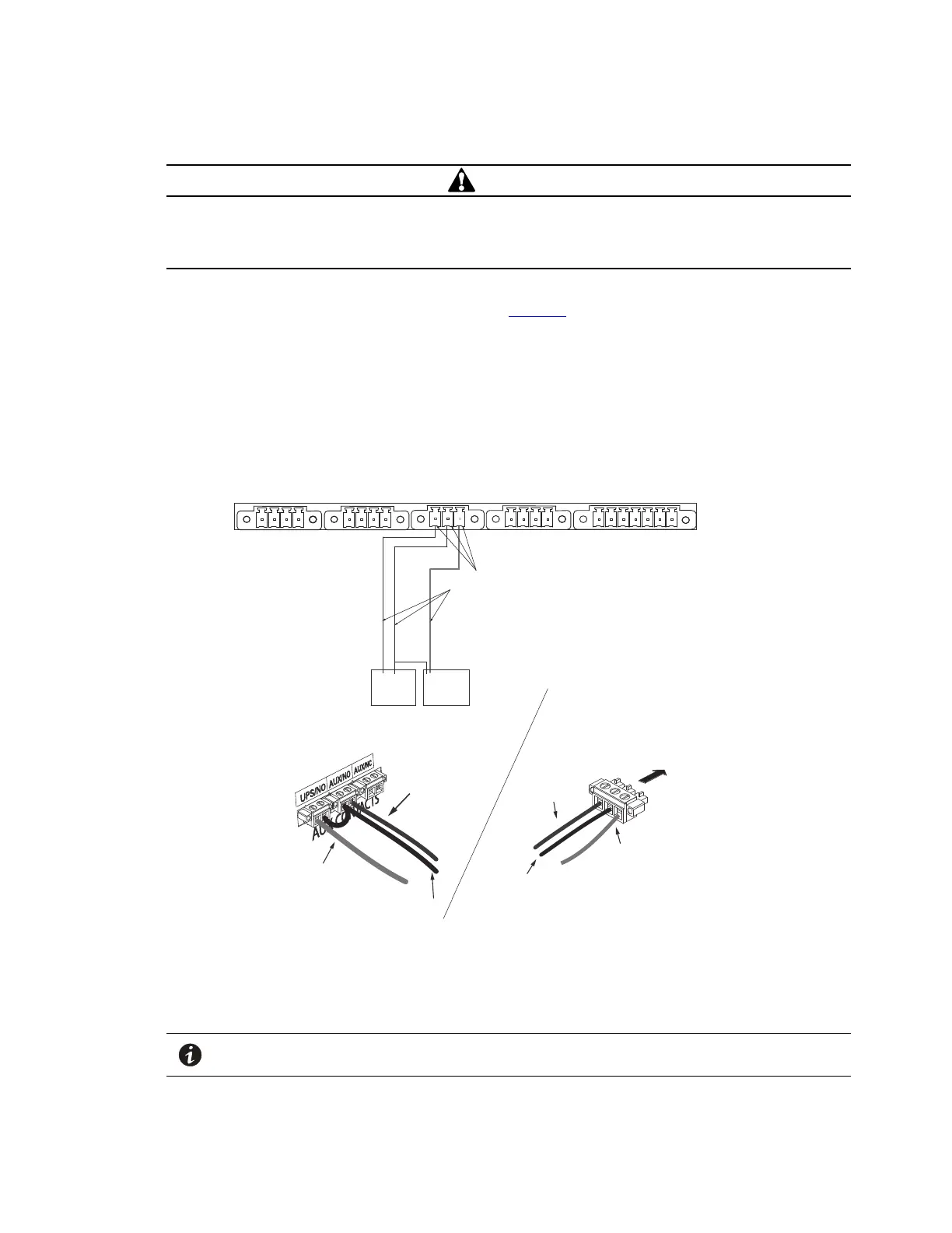
1. Route the maintenance bypass signal wires in a conduit from the bypass module to the communication
signal terminal (CN13) on the rear of the UPS ( See Figure 20 ). For conduit requirements consult your local
electrical code.
2. Place the signal wires through the proper conduit or grommet to the terminal block in the BPM.
Figure 20. UPS Input Control Signal Wiring for Maintenance Bypass
AUX NO
CONTACT
NO
CONTACT
ON UPS
(white wire)
BYPASS
NEUTRAL
(black wire)
FORCED
BYPASS IN
(red wire)
External CAN to EBM
(CN4)
Maintenance Bypass
(CN13)
EPO
(CN7)
3 2 14 3 2 1 4 3 2 1 4 3 2 1 7 6 5 4 3 2 1
Input signal
wires
ROO and On Generator
(CN6)
Building Input
(CN5)
Bypass Module
Terminal
BYPASS
NEUTRAL
(black wire)
FORCED
BYPASS IN
(red wire)
FORCED
BYPASS IN
(red wire)
BYPASS
NEUTRAL
(black wire)
Attach supplied
wire connectors to input wires
and plug into UPS
BPM Signal
Terminals
ON UPS
(white wire)
ON UPS
(white wire)
(Install conduit
over signal wires)
UPS Signal
Terminals
NOTE Do not strain relieve EPO or external bypass wiring with the same cable tie used for
Generator “On” wires.
BPM Signal Input Wire Routing