26 4–20kVA Users Guide P-164000669 4–20kVA Users Guide P-164000669—Rev 09
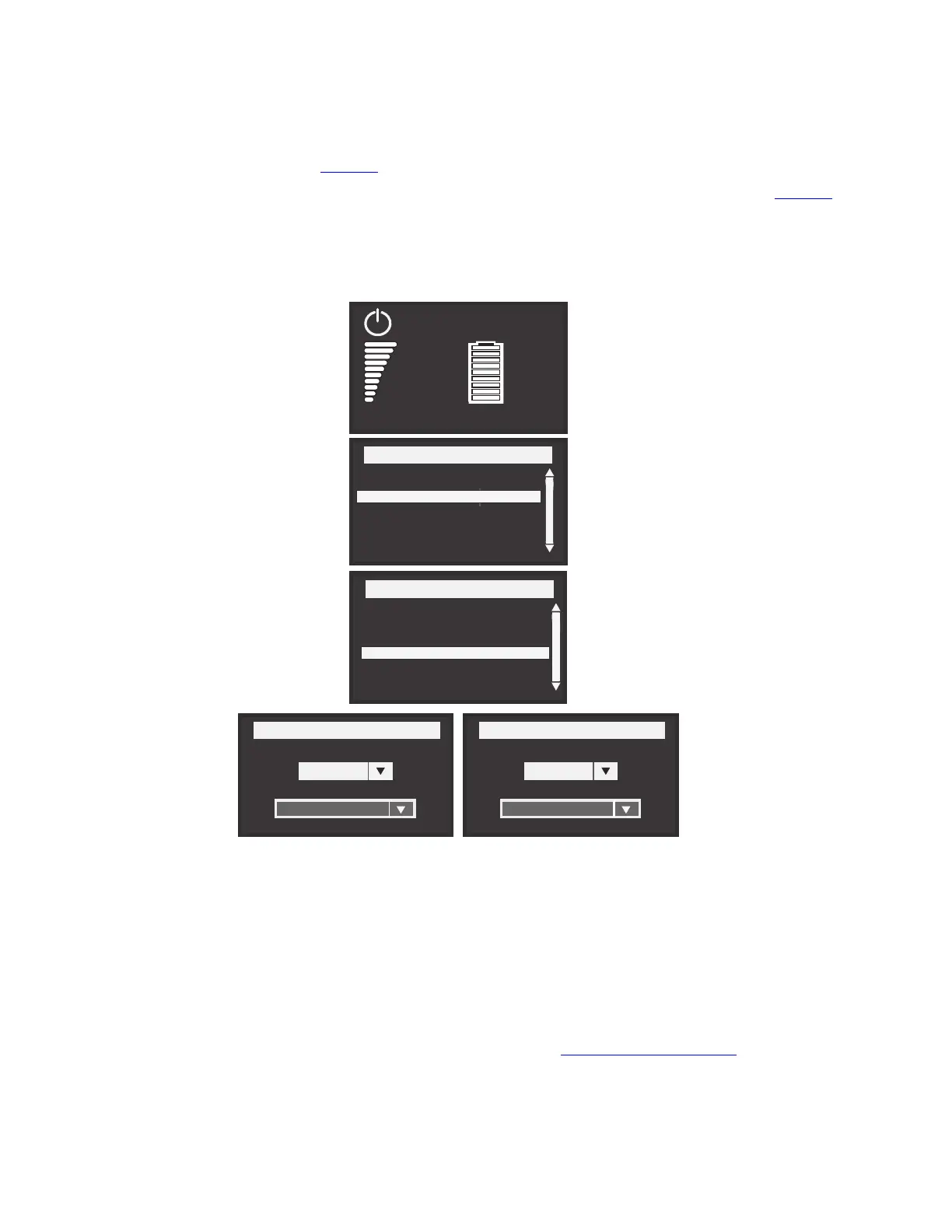
c. Navigate the 9PXM LCD to the forced and maintain bypass settings Input signals menu in the 9PXM
user guide (see Figure 23 ).
d. Set both Forced Bypass and Maintain Bypass settings to Enabled and Normally open (see Figure 23 ).
Figure 23. Forced and Maintenance Bypass Screens
Force Bypass
Dry contact setting
Enabled
Polarity
Normally open
Menu
Measurements
Control
Settings
Event Log
Fault Log
Identification
Register product
Settings
In/Out settings
Local settings
On/Off settings
Battery settings
Input Signals
Comm Settings
User Password Enable
User Password setting
Maintain Bypass
Dry contact setting
Enabled
Polarity
Normally open
Efficiency: 94%
0%
0.0kW
0.0kVA
100%
19min
1EBM
Load not powered
5. Install the supplied wiring connectors to the UPS input control signal wires and connect to the terminals as
shown in or .
6. When all connections have been made and checked, reinstall the bypass switch front cover using the
original screws.
7. If floor anchor brackets were installed and not secured, install the floor bolts.
8. After electrical installation is complete, you must also set the output settings menu for the required output
voltage as shown in the wiring configuration drawings (See 3.5 System Wiring Diagrams ).
BPM Signal Input Wire Routing