4–20kVA Users Guide P-164000669 4–20kVA Users Guide P-164000669—Rev 09 19
33..33 UUPPSS CCoonnnneeccttiioonnss
NOTE For installation and configuration of the Eaton bypass switch refer to the manual “Eaton
Bypass Power Module (BPM) User’s Guide P-164000628” supplied with the switch or
on the Eaton website
UPS Connections
NOTE 1 Refer to “ 3.2 Circuit Breaker Input Ratings” for breaker, terminal block, and wire sizing.
NOTE 2 Connection Diagrams can be found on Figure 17 and on Figure 18 .
CAUTION
To prevent electrical shock or damage to the equipment, verify that the Eaton 9PXM UPS is OFF before you
remove the terminal covers. The circuit breaker or disconnect switch must also be OFF at the AC input service
panel.
To install the UPS with an external bypass switch:
1. Mount the bypass switch within sight of the UPS. If you do not have an Eaton bypass switch or the fuse
box or panel is out of sight, you must install a separate disconnect switch next to the UPS.
2. The bypass switch should be mounted securely to a sturdy surface. You may need to turn the cabinet 90
degrees (on its side) to enable operator access to the switch handle.
3. Remove the six screws on the bypass switch wiring cover and remove the cover. Remove any packing
material inside the bypass switch.
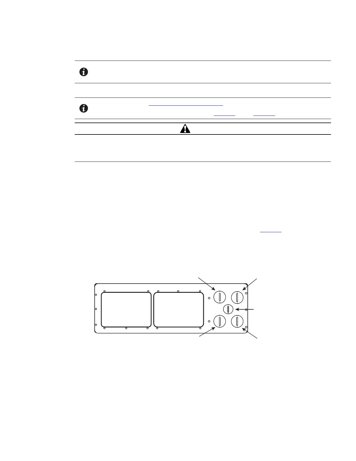
4. Remove the knockouts in the bottom of the BPM as needed for wiring. See Figure 15
Figure 15. BPM Bypass Bottom
From UPS Output To UPS Input
BPM Signal Wire
To Load
From Line
UPS Connections
 Loading...