48 4–20kVA Users Guide P-164000669 4–20kVA Users Guide P-164000669—Rev 09
NOTE DC input cables only required if EBM(s) are installed upstream.
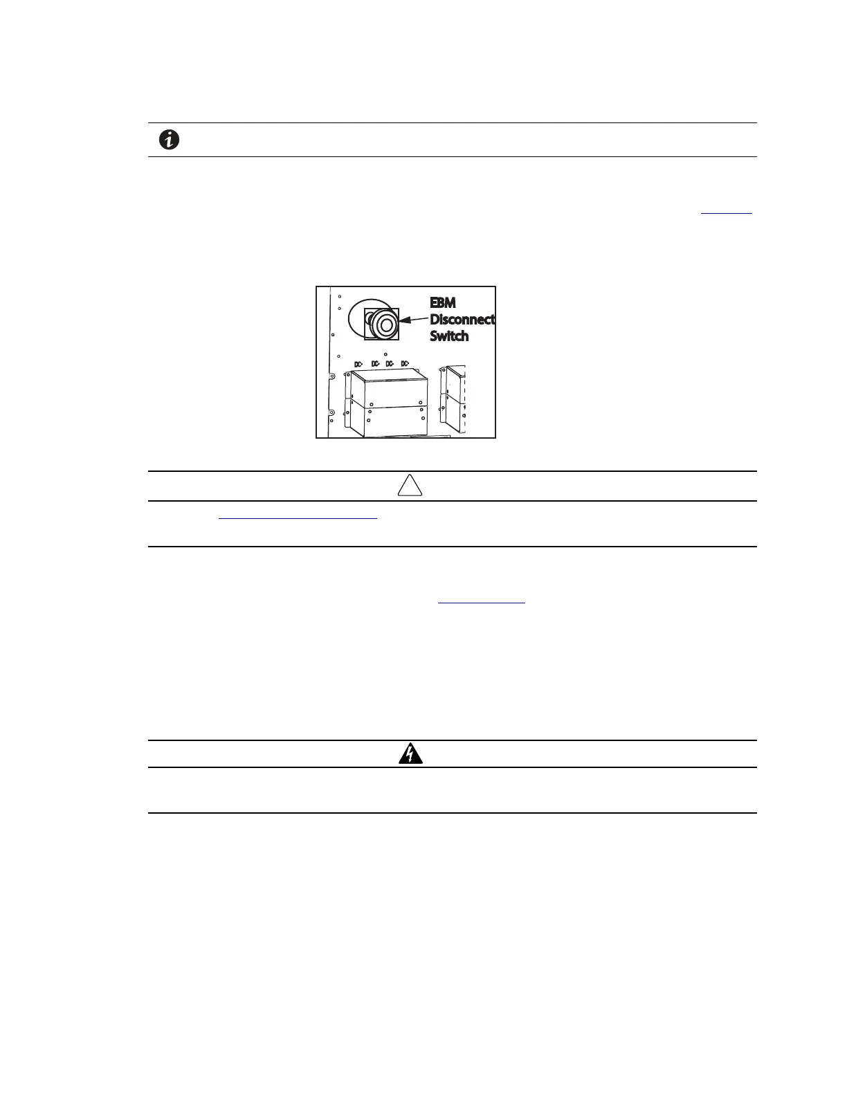
5. Close the DC emergency disconnect switch button on the back of each EBM. Insert the switch key
supplied with the cabinet into the button and turn clockwise 1/2-turn. Pull the button OUT to close the
switch and reconnect DC power. Turn the key back counter-clockwise, and remove the key (see Figure 41
).
Figure 41. EBM Emergency Disconnect Switch
IMPORTANT
Continue to "6.5 Initial Startup Parameters” to set the number of external battery strings on the UPS LCD for
calculating the runtime.
55..22 CCoonnnneecctteedd BBaatttteerryy CCaabbiinneett OOppttiioonn
If you are not installing optional battery modules (EBM), continue to “6.1 UPS Startup ”.
The Advanced Battery Cabinet for the 9PX allows for the following enhanced installation options:
• No AC Input Option: For use for Extended Run-Time Battery Support only.
• 120VAC Single Phase Input Option :UPS Communication Capable and Extended Run-Time Battery
Support.
• 120V/208V or 120V/240V Split-Phase Input: Super Charger Capable, UPS Communication Capable and
Extended Run Time Battery Support.
WARNING
Only qualified service personnel (such as a licensed electrician) should perform the battery cabinet installation.
Risk of electrical shock.
Connected Battery Cabinet Option
 Loading...


