4–20kVA Users Guide P-164000669 4–20kVA Users Guide P-164000669—Rev 09 47
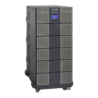
Figure 39. Battery Cable Installation For Standard EBM(s)
Screws
Cover
DC+ DC- DC- DC+
To UPS
DC input cables from
upstream EBM
(if installed)
Terminal
Block
NOTE Torque the screws holding all input and output power conductors to the values specified
in Table 2 .
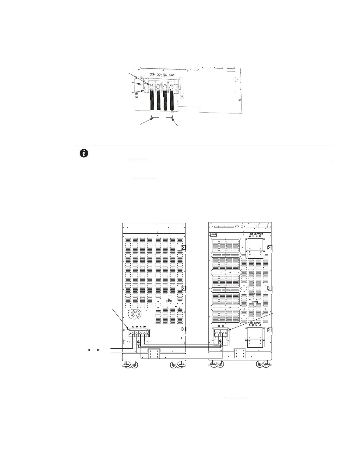
2. Connect the EBM DC Cables to the applicable terminals by removing and reinstalling the screws onto the
terminal blocks. See Figure 40.
3. Reinstall the AC and DC terminal covers.
Figure 40. Standard EBM to UPS Connections
EBM Terminal
Blocks
UPS/EBM
Terminal
Block
From previous
EBM
(if installed)
CN4
EBM UPS
DC+
DC-
DC+
DC-
4. If additional battery cabinets are to be connected to the first, in a daisy-chain configuration, connect each
EBM with the DC cables supplied in the EBM accessory kit. Figure 40 ).
Standard Battery Cabinet Installation
 Loading...