52 4–20kVA Users Guide P-164000669 4–20kVA Users Guide P-164000669—Rev 09
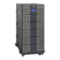
Figure 44. Battery Cable Assembly Installation
Screws
Screws
Ground
Lug
Cover
DC+ DC- DC- DC+
G L1 N L2
To UPS
DC input cables from
upstream EBM
(if installed)
Terminal
Block
Terminal
Block
To Dedicated 30 Amp
Circuit.
NOTE Torque the screws holding all input and output power conductors to the values specified
in Table 2 .
2. Connect the EBM DC Cables to the applicable terminals by removing and reinstalling the screws onto the
terminal blocks.
NOTE DC input cables only required if EBM(s) are installed upstream.
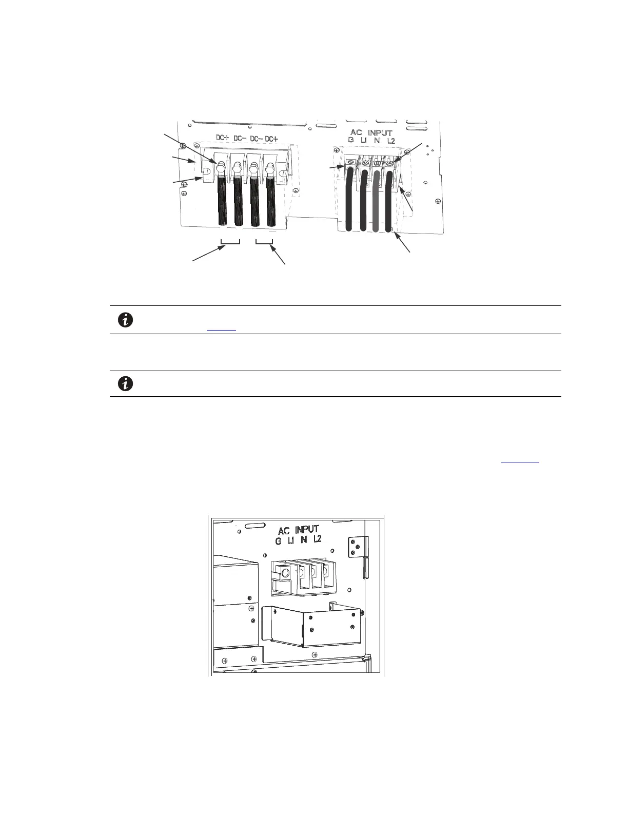
3. Connect the AC cables to the applicable terminals by inserting the ends into the AC terminal block and
tighten the screws depending on the EBM configuration option as follows:
Option #1
No AC Input :Extended Run-Time Battery Support option with no UPS communication (see Figure 45 ).
Figure 45. No AC Input
Option #2
Connected Battery Cabinet Option
 Loading...