58 4–20kVA Users Guide P-164000669 4–20kVA Users Guide P-164000669—Rev 09
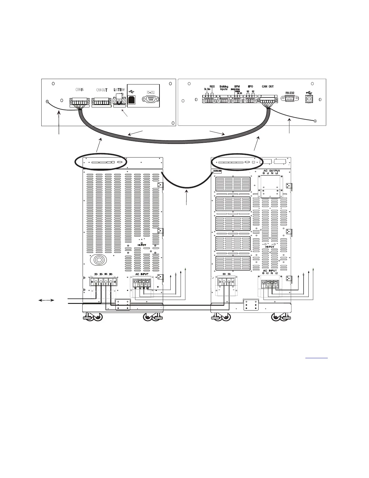
Figure 51. CAN Communication Wires UPS to EBM
From previous
EBM
(if installed)
CN3CN4
CN4
EBM
UPS
To AC
supply for
super
charger
(if installed)
DC+
DC-
DC+
DC-
L1
G
N
L2
Grey EBM CAN Communication Cable
2 17 117
CN3
CN4
CAN IN
CAN OUT
LAST EBM
JUMPER
NOT FOR CUSTOMER USE
RS-232
Secure Green and Yellow CAN
cable ground wire to the chassis
Green Terminal Jumper
in Last EBM
L1
G
N
L2
EBM 1
UPS
Secure Green and Yellow CAN
cable ground wire to the chassis
Chassis Ground
Wire
13. Close the DC emergency disconnect switch button on the back of each EBM. Insert the switch key
supplied with the cabinet into the button and turn clockwise 1/2-turn. Pull the button OUT to close the
switch and reconnect DC power. Turn the key back counter-clockwise, and remove the key (see Figure 52
).
Connected Battery Cabinet Option
 Loading...