AUX
CONTACT
WHITE WIRE
COMBINE BLACK WIRES
RED WIRE
NO
CN13
3
2
1
2
2
3 7
4
5
3
1
CN3
CN4
CN6
CN6
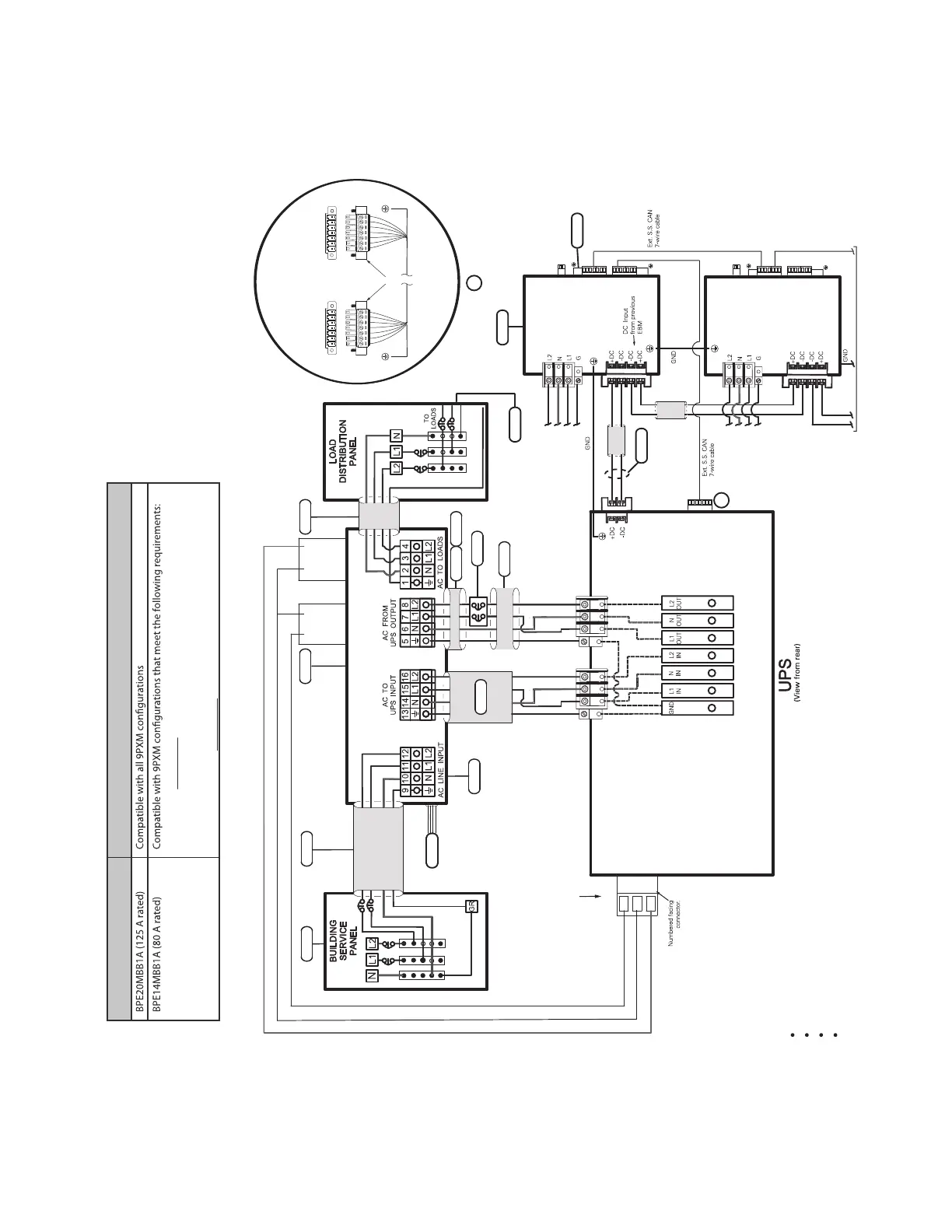
110/220 Input, 110/220 Output
120/208 Input, 120/208 Output
120/240 Input, 120/240 Output
127/220 Input, 127/220 Output
OUTPUT POWER
BUS BAR
AC OUTPUT
AC INPUT
EXTERNAL BPE
MBB Option
(Maintenance Bypass)
3
2
3
UPS INPUT
SIGNALS
6
7
AC INPUT
TO EBM 1
AC INPUT
TO EBM 2
TO NEXT EBM
(If installed)
DC
INPUT
EBM 1
}
EBM 2
CN3
CN4
8
9
7 6 5 4 3 2 1*
7 6 5 4 3 2 1
UPS
CN4
EBM
CN4
Supplied
Connectors
*Pin numbering
is right-to-left
Input Signal connections
(Typical)
A
A
G
L2L1 N
G
L2
L1
N
NO
CONTACT
Force Bypass Red Wire
Common Black Wire
On UPS White Wire
2. (3) UPS’s (9PXMSPPM) split-phase power modules and
(1) Supercharger (9PXMCHGR) or less installed in a 9PXM UPS*.
Legacy Bypass 9PXM Compatibility
1. (4) UPS’s (9PXMSPPM) split-phase power modules or less
installed in a 9PXM UPS*.
*Since BPE14MBB1A is rated for 80A you cannot install more than 80A of 9PXMSPPM split-phase power modules and
9PXMCHGR battery modules into a 9PXM UPS. Each 9PXMPPM split-phase module and 9PXMCHGR battery charger
module is rated at 20A maximum current.
 Loading...


