Type VSA12, VSA16 and VSA20/800 maintenance instructions
7 MAINTENANCE INSTRUCTIONS MN280064EN October 2017
5. Loosen bolts that secure upper interrupter clamp. As
clamp is loosened atmospheric pressure, acting on
the bellows, will cause the contact rod to move down
into interrupter. This action can be verified by observing
the scribe mark on the contact rod. It should move
down, toward contact rod support plate, when clamp
isloosened.
Upper
interrupter
clamp
Insulating
barrier
Nyliner
bushing
Stringer
Nylon hardware
Long
bushing
lead
Wire tie
Insulating
barrier
Bushing
lead clamp
assembly
Clamp
hardware
Stringer
hardware
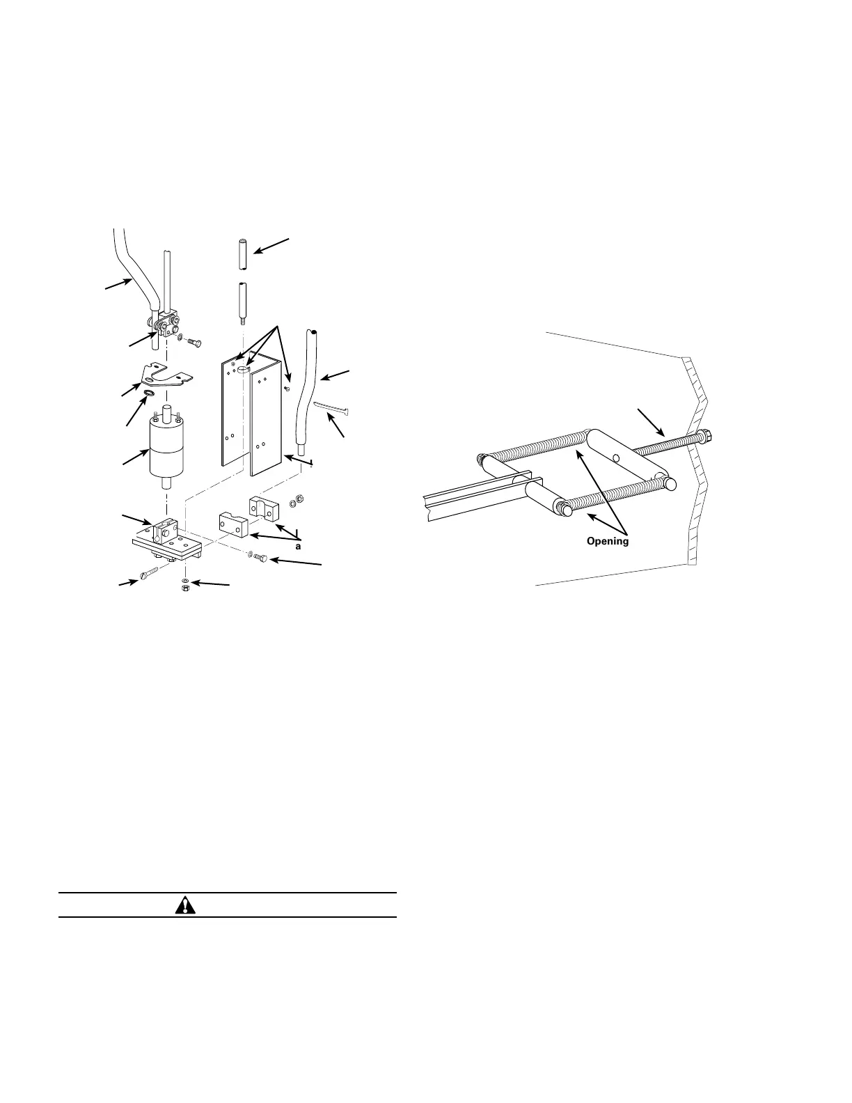
Figure 8. Vacuum interrupter replacement
ote:N If contact rod does not move, interrupter may have
lost vacuum, or the contact rod may be sticking
within the clamp. Use a screwdriver to gently spread
clamp to free rod.
6. Remove hardware attaching lower current exchange
plate to stringers. Carefully lower plate and vacuum
interrupter assembly from between stringers.
7. Loosen lower current exchange clamp and remove
interrupter. If stationary contact rod sticks within clamp
use a screwdriver to gently spread clamp to free rod.
8. Remove insulating barrier from top of old interrupter
and install on new interrupter.
9. Install stationary contact rod into lower current
exchange plate, do not tighten clamp hardware.
CAUTION
Interrupter damage. When installing the moving contact
rod into the upper clamp avoid twisting or cocking
the rod. Excessive force can damage the bellows,
causing loss of vacuum and irreparable damage to the
interrupter and/or premature interrupter failure.
10. Carefully place interrupter and lower current exchange
assembly into position; situate moving contact rod
within upper clamp as assembly is installed. Install
washers and locknuts to secure lower current exchange
plate to stringers.
11. Loosen tension bolt to relieve opening spring tension,
Figure 9.
12. Manually close recloser.
13. Tighten top and bottom contact rod clamp hardware to
20-22 ft-lbs torque.
14. Tighten tension bolt to re-apply tension to opening
spring, Figure 9.
Figure 9. Opening spring tension bolt
15. Install clamp and hardware to secure long bushing lead
to lower current exchange assembly and tighten.
16. Manually trip and close recloser several times to check
operation.
1 7. Install insulating barrier and secure with nylon
hardware, or wire ties, as applicable
18. Perform Insulation Level Withstand Test (see page 8).
19. Install fused pullout switch to energize AC power
source to operator mechanism.
Operating mechanism
The spring operated mechanism uses solenoids to release
charged opening and closing springs. The closing springs
are charged by a motor-gear reduction drive. The closing
operation charges the opening springs.
The upper portion of the operating mechanism in the
operator cabinet incorporates the tripping mechanism
which includes the trip solenoid, mechanical linkages and
associated switches. The lower portion of the mechanism
incorporates the closing mechanism which includes the
close solenoid, motor, gear reduction drive, clutch, closing
springs, mechanical linkages and associated switches. The
opening springs and the linkages to operate the interrupters
are located under the head of the recloser.
Tension
bolt
Opening
springs

 Loading...


