Type VSA12, VSA16 and VSA20/800 maintenance instructions
11 MAINTENANCE INSTRUCTIONS MN280064EN October 2017
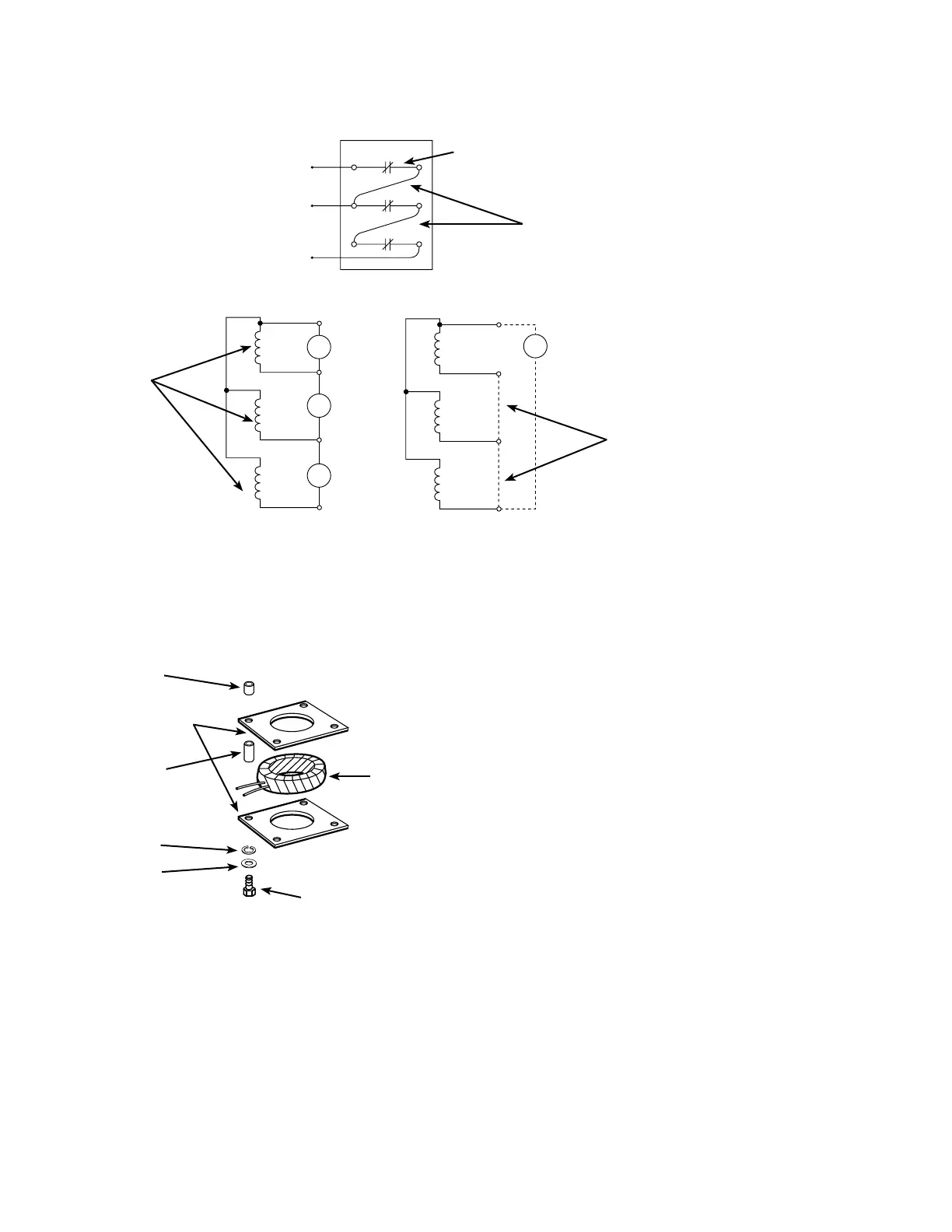
Recloser contacts in
closed position
1
2
A
B
C
MA
MA
MA
K
G
H
J
A
B
C
K
G
H
J
MA
100 AMP AC test
circuit
Test leads connecting
phases in series
Control cable
receptacle sockets
Sensing CT’S
Ratio test circuit (A) Polarity test circuit (B)
Test leads connect
bushing CT
secondaries in parallels
Figure 16. Test circuit for checking bushing current transformers
Sensing-current transformer replacement
To replace a damaged current sensing transformer proceed
as follows, refer to Figure 17.
Spacer
Coil retainer plate
Washer
Lockwasher
Sensing CT
Capscrew
Figure 17. Current sensing transformer replacement
1. Remove bushing that passes through the current
transformer that is to be replaced.
2. Label sensing current transformer leads. Use labeling in
accordance with connection diagram. The X1 leads are
white and the X2 leads are black.
3. Cut leads, on transformer side of the original splice, to
disconnect current transformer.
4. Remove capscrews that secure current transformers Remove
and discard damaged sensing CT; retain coil retainer plate.
ote:N Sensing CTs are marked with a black spot to indicate
polarity, when installing the replacement CT orient
the black dot to match the dot on the other CTs that
are already installed.
5. Install replacement CT, secure with hardware removed.
6. Trim CT leads as required. Slide shrink tube over each
lead, splice connection and solder. Slide shrink tube
over splice and apply heat to shrink. When splicing
connections, refer to previous labeling to assure proper
leads are connected before soldering.
7. Install bushing assembly.
8. Perform the ratio and polarity tests after replacement of
any sensing CT to make sure they are properly installed.
Control cable check
With the cable removed at the control, use an ohm meter to
check the continuity of each circuit through the connection
at the operator cabinet up to the control terminal block.
The connector pin sockets and the control terminal block
are lettered correspondingly. Remove and replace each
conductor at the control terminal block while checking.
A zero reading will indicate continuity, an infinite reading
indicates an open circuit. Continuity between terminals and
unlike pin socket indicates a shorted circuit. Replace if cable
is damaged.
Control circuit components
The operating sequence of the various circuit components
is diagrammed in Figure 18. See Figures 19 and 20 for
connection diagrams and wiring tables. A schematic

 Loading...


