Type VSA12, VSA16 and VSA20/800 maintenance instructions
2MAINTENANCE INSTRUCTIONS MN280064EN October 2017
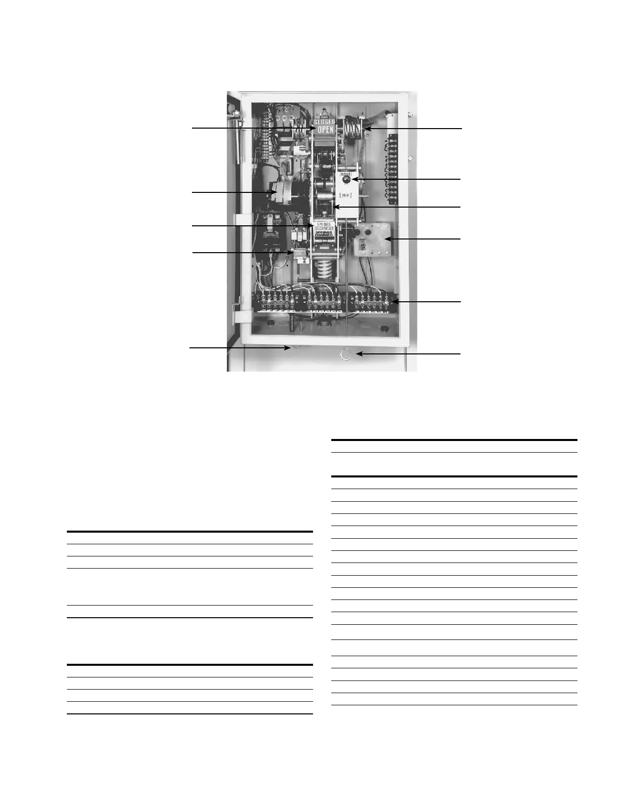
Contact position indicator
Drive motor
Spring charge indicator
Manual close lever
Manual close lever
Auxiliary switch (accessory)
Trip-reset knob
Operation counter
Operator cabinet heater
Manual trip lever
Multi-ratio current transformer
terminal board (accessory)
Figure 2. Operating mechanism
Specications and ratings
The recloser will interrupt fault currents only when applied
within its specified ratings. Consult the following ratings
and compare to system characteristics at point ofapplication
prior to installation.
Table 1. Voltage ratings
VSA-12 VSA-16 VSA-20
Maximum design voltage (kV) 15.5 15.5 15.5
Nominal operating voltage (kV) 2.4-14.4 2.4-14.4 2.4-14.4
Basic insulation level (BIL) (kV) 110 110 110
60 Hertz withstand voltage (kV)
Dry, one minute 50 50 50
Wet, ten seconds 45 45 45
Max RIV at 1.0 MHz/9.41 kV (mV) 100 100 100
Table 2. Duty cycle
Percent of maximum circuit
interrupting rating
Maximum
X/R ratio
Number of unit
operations
15-20 4 88
45-55 8 112
90-100 15 32
Total 232
Table 3. Mechanical life
Open-close, no load, operations 2500
Table 4. Electrical specifications
Trip solenoid:
Operating voltage (Vdc) 24
Peak current (A) 12.2
Actuation time (cycles (ms)) 1.25 (21)
Close solenoid:
Operating voltage (Vdc) 24
Peak current (A) 15.5
Actuation time (cycles (ms)) 1.5 (25)
Spring charging motor:
Standard Accessory
Operating voltage (Vac) 240 120
Voltage range (Vac) 190-257 90-127
Maximum current, rms (A) 14 18
Steady state current (A) 4.1 9
Running time (cycles (S)) 40 (0.67) 40 (0.67)
DC resistance, nominal:
Bushings, terminal-to-terminal (mW) 120
Interrupter, terminal-to-terminal (mW) 29

 Loading...


