Installation and commissioning
[18]
measuring amplifier directly at the cable inlet of the control cubicle. Moreover, connect
the outer cable shield to protective earth as often as possible, for example, at every
intermediate distribution frame or cable gland.
A higher electromagnetic compatibility can be achieved by connecting the cable shield to
protective ground at either end of the cable – provided that no ground loop current
(equalizing current) occurs.
The maximum cable length, for installation in non-hazardous locations, between an EZ
1000 and a measuring amplifier, such as an A6500-UM card, depends on the electrical
properties of the used cable.
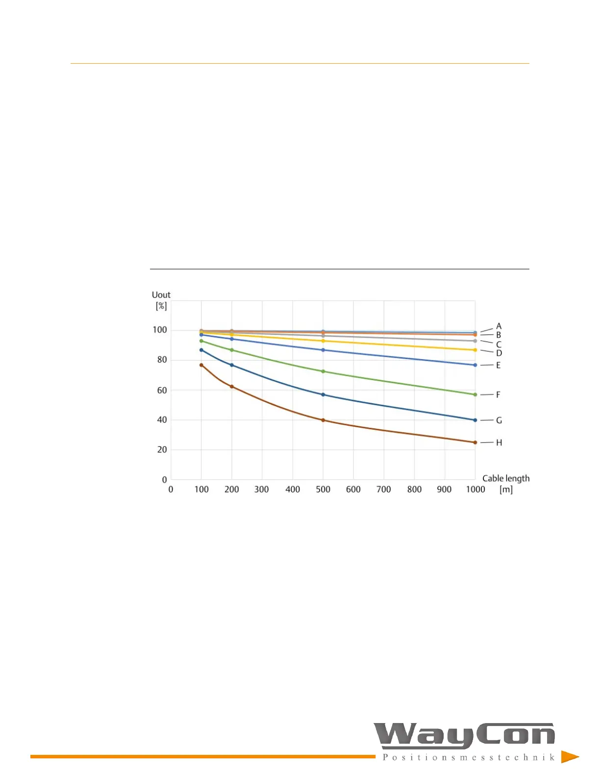
Figure 5-3
explains the influence of the used cable on the
output signal of the EZ 1000. The signal frequency has the most significant influence on
the maximum cable length. The higher the signal frequency and the longer the cable, the
higher the signal damping.
Figure 5-3: Cable influence on the converter output signal
Cable capacity 120 nF/km (wire/wire); signal frequency:
A.
100 Hz
B.
200 Hz
C.
500 Hz
D.
1000 Hz
E.
2000 Hz
F.
5000 Hz
G.
10000 Hz
H.
20000 Hz
Example: At a signal frequency of 1000 Hz and a cable length of 1000 m, the converter output voltage is
reduced by approximately 13%.
The accuracy of the calculated U
out
values is ±10%.

 Loading...